


A large overhang on a Dutch Hip roof requires a few changes to the normal construction method.
In 2011, I was given the opportunity to frame up four small houses with Dutch Hip roofs on a remote island in the tropics. I planned to use the experience to teach the contractor’s crew western style framing.
The houses were designed in a style that was used by the US military in the Gamboa region of the Panama Canal Zone.
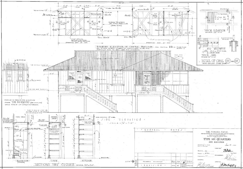
Panama Canal Zone Gamboa Design (Note: Click any image to enlarge)
This style is very effective in the tropics. It incorporates huge overhangs to provide both abundant shade from the brutal sun and extra coverage around the house for the torrential rains during the monsoon season (averages of nearly 20 feet of rain per year). During the day, while I was there, temperatures in the shade were always in the 90s accompanied by skin-soaking humidity of 90% or higher. Only at night did the temperatures become bearable in this carpenter’s honest opinion.
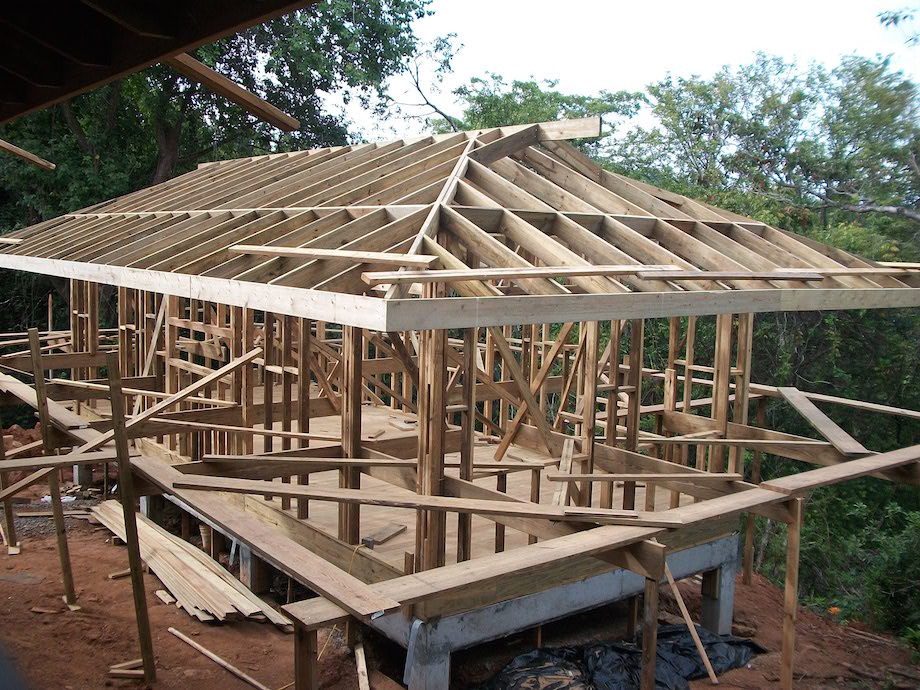
The buildings were relatively narrow with 10-ft. tall exterior walls. The ceiling was “open frame” style, 2×8 rafters/ridge at 5/12 pitch with 1x T&G decking above. The Dutch Hip’s tiny gable end walls were only to be perimeter framed then screened off to serve as roof vents. During the day, the tropic sun would bake the metal roofing, which in turn would transfer some of its heat to the air below the sheets and that hot air seeking to rise would find its way out these vents. The rising air would draw cooler air in through the windows, facilitating a constant movement of air through the house, somewhat like how a chimney draws air up and out of the fireplace. The interior partition walls were 8-ft. tall and open above to the roof, similar to work station cubicles in a large office. All the framing was to be done with imported treated Honduran pine, some strange wood that I had never heard of before. I sure hope it works, since in this climate, mold and termites can knock an untreated wood structure down almost as fast as one can put it up.
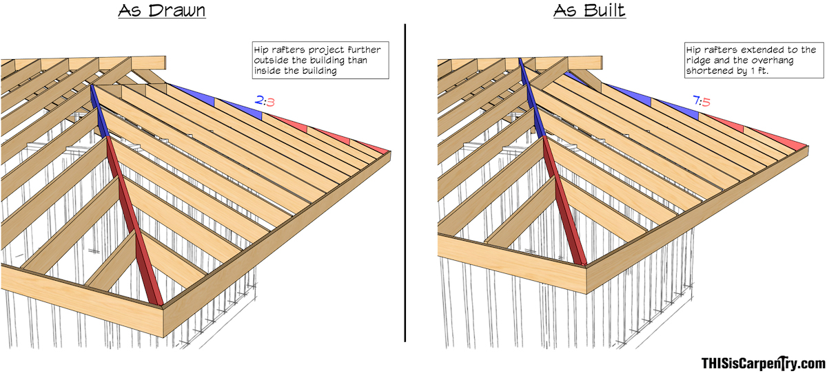
Reviewing the plans, I noticed that the ratio of eave’s overhang distance to common rafter run was near 1:1. While in latitudes farther to the north this would cause snow-loading problems, in the tropics—where lightweight metal roofing is the norm and nothing other than rain (or perhaps an occasional coconut) loads the roof surface—one would suffer no dire consequences from the design. Of course, with tails that long, one could anticipate a struggle when running the fascia. With the birdsmouth located mid length along the rafters and the rafters themselves having varied sized crowns, you can easily imagine the extra time that will be involved in jockeying the tails up/down to create a straight fascia line.
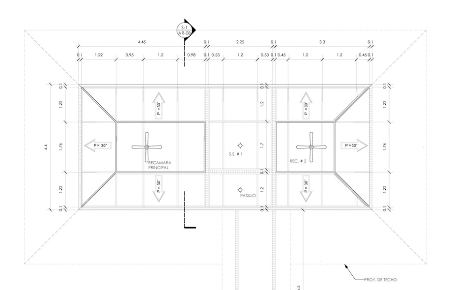
Original roof plan
I observed that the architect had drawn the Dutch Hip ends to be framed in the standard method where short hip rafters frame to butt into a set of paired common rafters positioned at some distance in from the end of the building.
Normally Dutch Hip overhangs are relatively short as compared to that part of the Dutch Hip framing set inside the building. Most architects and engineers like to use a 1:2 or better cantilever ratio favoring the inside in these situations. In other words, that part of the Dutch Hip framed inside the house is at least two times the length of the eave’s overhang. As a bare minimum, they want to see no less than a 1:1 ratio unless a counterbalancing force is incorporated. But in this case, the cantilever ratio was reversed with much more rafter length hung outside the building than the Dutch Hip framing protruded inside the building. There was 6 ft. of overhang versus only 4 ft. of rafter length inside the building. This was a major structural concern since the hip rafter tail alone would serve as the primary support for a 6′ x 6′ roof section (36 sq. ft.). Evidently it had slipped by the architect unnoticed.
What I decided to do was get permission to shorten the overhang distance by 1 ft., making it a total of 5 ft. instead of the called out 6 ft., and then I would run the Dutch Hip’s “hip rafters” full length up to the main ridge rather than butting them into a set of paired common rafters. I would use continuation jack rafters to frame in the small gable-like extension that is an integral part of the Dutch Hip design. By doing this, it changed the “as drawn” cantilever ratio of 3:2 favoring the outside of the building to a 5:7 ratio favoring the inside of the building. Personally, with the big eaves, I would have liked to see doubled 2x8s used as the hip rafters versus the specified single 2×8. But since I was only there to help with the framing, not redesign the buildings, I decided to stay out of the architect’s realm unless I saw blatant errors.
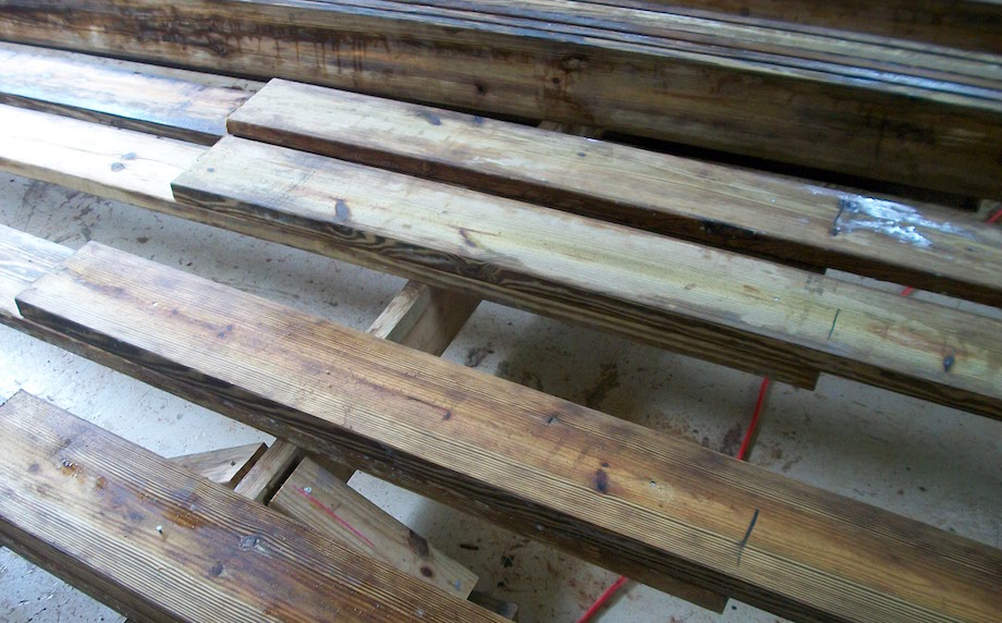
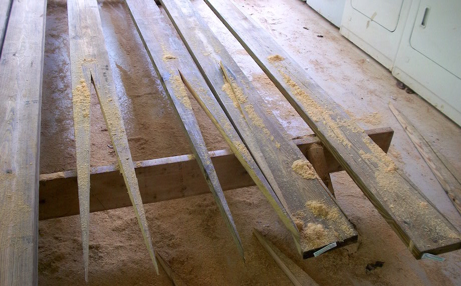
The material for the hips had been delivered per the original drawings. With my change, they would now be short to reach the main ridge. To reorder longer lengths would delay the project more than a month so I chose to “stretch” those boards by structurally joining them to another piece of 2×8 using a dovetail joint.
| Step 1: Overlay and mark |
 |
| Step 2: Cut |
 |
| Step 3: Assemble |
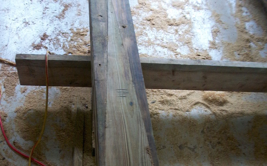 |
The dovetail joint is detailed in A Roof Cutter’s Secrets, on page 115. Click HERE to view a short video clip from the second DVD of the “Roof Framing for the Professional – the Essentials” video series, in which I demonstrate making the dovetail joint to join two boards together to form a long ridge.
While I did not specifically detail how to do this special type of Dutch Hip framing in A Roof Cutter’s Secrets (RCS), the book nonetheless includes all the background information needed to accomplish the task. Cutting regular hip rafters are shown on pages 63-67, so nothing new here. Continuation jacks are nothing more than regular valley jacks (RCS pages 97-98) installed from a ridge to a hip, versus their normal usage from a ridge to a valley, so nothing new here either—just a different application (continuation jacks are pictured on page 105 of RCS). The gable-like extension at each end of the ridge could also be framed in layover style using CA valley jacks (RCS pages 97-98) if the full hip end was sheathed all the way to the ridge. That wasn’t an option on this project since the roof surface under the gable-like extension was to be left open for venting purposes.
Click HERE to view another short video clip from the first DVD of the series, where I actually spend a minute in the classroom presenting this particular “hip to main ridge” Dutch Hip framing method.
So for these four houses, I ran the main ridge well past where the full-length hips would tie in so I could incorporate the gable-like extension. With the ridge run long at each end of the building, there would be no standard “end-of-ridge” king common rafters to position the tops of the hips during stacking, so I pulled up a temp “end-of-ridge” king common rafter (reg. common for the main span) to use as a marking guide. I slapped it alongside the ridge and pulled the birdsmouth tight against the outside wall, then scribed the head-cut when the top corner edge flushed with the main ridge. After transferring this plumb line up and over the top edge of the ridge to mark the opposite side, I used math to locate the hip intersection plumb lines at the far end of the ridge. Recall that the distance along the ridge between those two sets of plumb lines would be the same dimension as if the ridge had been cut to an exact length for a full hip situation (RCS pages 63-64). The math to calculate that length is:
Building length – building width + thickness of the ridge = the actual ridge length
When stacked, the top centers of each pair of hips position on these lines. RCS page 123 shows proper alignment of the top long point edge of a single cheek hip at the top edge of the ridge.
| The edge of the hip flushes with the ridge. | 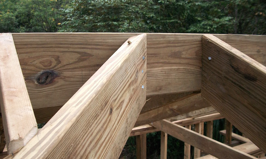 |
When stacking the hips, plumb and brace the bottom of the hip at the outside wall corner. This will make installing hip jack fill much easier.
 |
The hip rafter plumbed and braced at the outside corner. |
After we had the roof skeleton up (a few pairs of setup commons plus the hips), we went back and installed the hip jacks, the common rafter fill, and ran all the frieze blocks. Since the frieze blocks were exposed, they were placed at 90 degrees relative to the top surface of the rafter abutting the outside wall. As most know from RCS, I start my jack layout from the building corner with exposed frieze blocks as this negates having to install a tricky frieze block with a double compound miter at the hip rafter.
| The step hip jacks larger from the corner to simplify frieze blocking. | 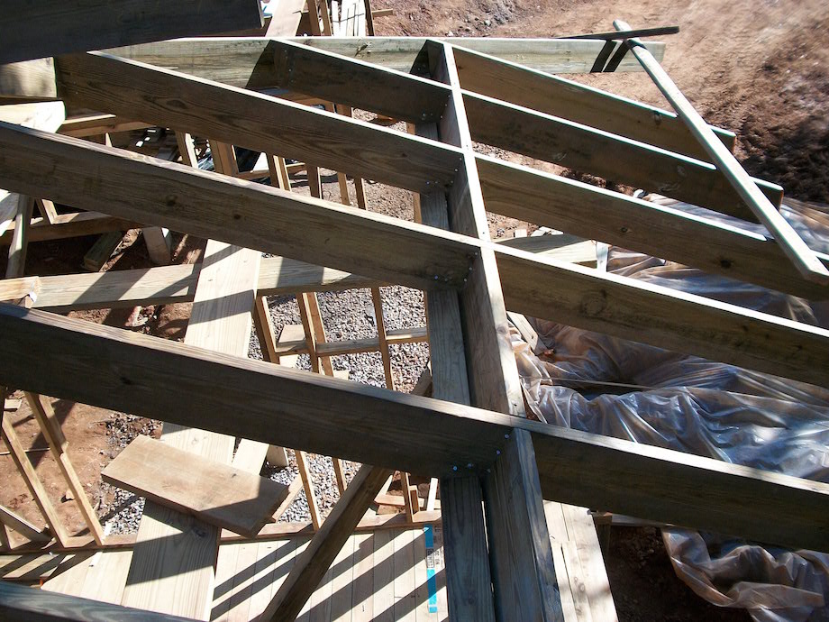 |
Now it was time to finish off the little gable-like extensions at each end of the ridge by installing the continuation jacks.
Because I had to run the hip jacks full-length on the ends of the buildings to strengthen the dovetailed hip rafter (rather than heading them off at the gable extension)…
| …the 45-degree cheek-cut at the bottom of the continuation jacks needed to be clipped slightly to fit. | 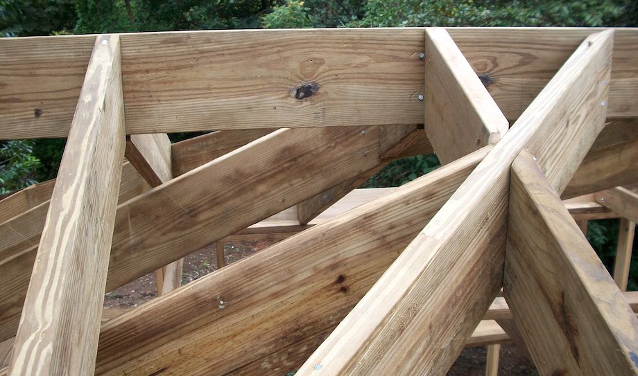 |
Remember these jacks must plane in with the far side of the hip, so hold them up accordingly.
 |
The continuation jacks are used to help frame the Dutch Hip end. |
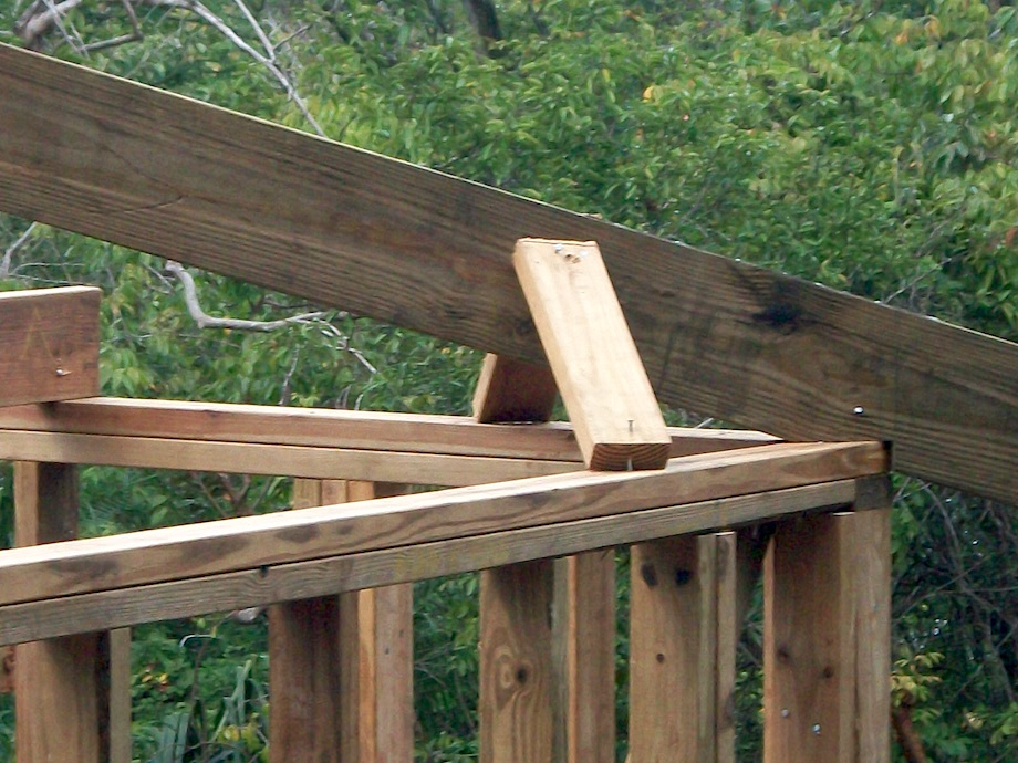
Since the overhang was so large, we had to straighten the hip rafter tails with long cleats run from the installed hip jacks. This cleat also facilitated installation of the flyer hip jacks located along the hip tail.
| 2×4 cleats are used to straighten the hip and support the flyer jacks. | 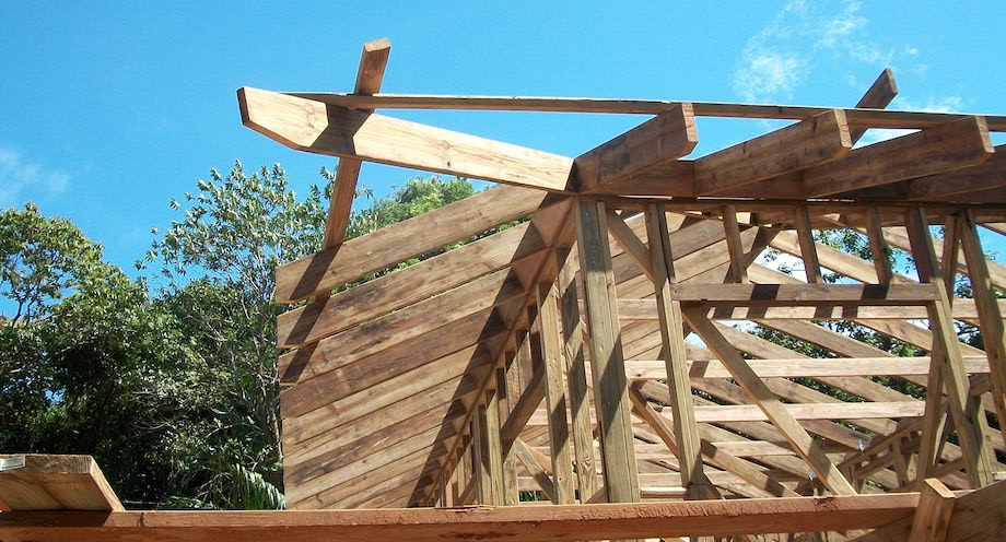 |
We utilized the 2x fascia to help carry some of the eave’s corner load by hanging full-length 20-ft. pieces along the sides of the building that reached out to the hip tail corner. This “diving board effect” works even better if the fascia crown is placed down.
Long pieces of fascia along the building sides help with corner load.
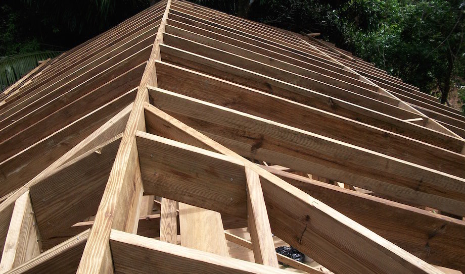
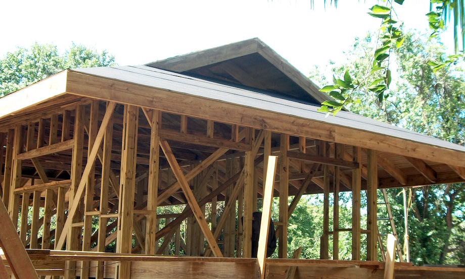
With the 1x roof decking installed, the building really came together.
This shows the completed roof framing with 1x decking installed:
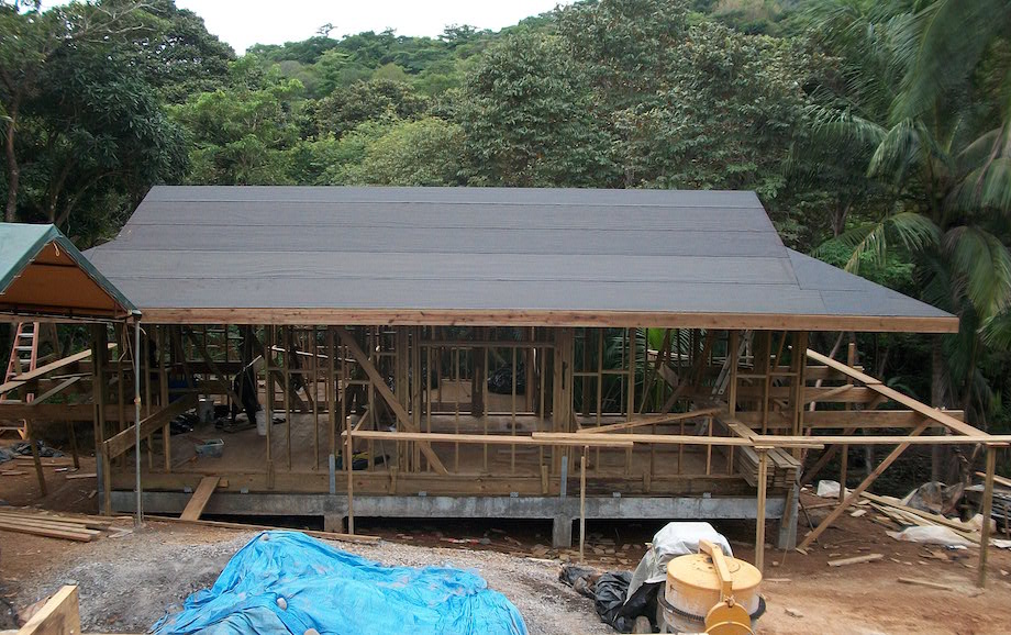
And here you’ll see the scaffolding to work the eaves, which was set up 6 ft. 4 in. from the building walls to the center:
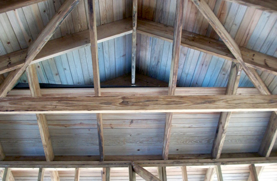
And finally, here’s an inside view of the large Dutch Hip roof vent:
• • •
AUTHOR BIO
 Will Holladay is one of the housing industries most respected and beloved roof cutters. His life story rings of hard work: from a shovel totting jobsite laborer to a housing tract roof stacker/cutter (Los Angeles CA, 70s), to a high-end custom home framing contractor (CA Coast, 80s-90s), to a freelance roof framing consultant (USA and abroad, 2000s and on). Will’s 4+ decades of “hands on” framing experience is the basis for his various literary works: the classic framing manual A Roof Cutters Secrets (‘89, ‘02, ‘12), which some say revolutionized modern day framing; A Roof Cutter’s Secrets DVD (‘97); The Complicated Roof – a cut and stack workbook (‘09); “Roof Framing for the Professional” DVD series (‘12). Will was a contributing author for JLC from the mid-90s through the early 2000s, and gave demos and taught roof-framing clinics at many JLC LIVE conferences. Will has invented several labor saving roof cutting tools including “The Headcutter” (a saw foot for chainsaws ‘96), and “The Roof Cutter’s Birdmouth Guide” (‘11). Since the early 2000s, Will has spent the majority of his time overseas helping as a volunteer in various capacities, including teaching young men rough carpentry skills. He can be found on the internet at www.theroofcutter.blogspot.com, where there are links to purchase his books and videos.
One of the many wonderful aspects of This is Carpentry, is finding people from the past. Sort of an online “is he/she still alive” type service.
Seeing the Will Holladay article on Dutch Hips brought back several such memories. Great article from a great craftsman.
Craig Savage — still alive — barely
While in the Navy, in the Philippians, I stayed in military housing similar to this. It worked very well. During the rainy season it poured straight down every morning until about 9:00 am. Then the sun came out and the steam rose! But the nights were pleasant with great ventilation and often nice breezes.
Will,
I was glad to find your article on Dutch Hips through JLC Online. I have on my desk your ’89 version of A Roof Cutter’s Secrets. Even though I’m not doing much roof framing now (at 66), I’ve always been thirsty for the technical side of how to cut the pieces and assemble them correctly for a roof you can be proud of.
And Craig Savage, good to see you still out there in the world also. Remember when we did an article on my rolling door hanger’s bench for JLC back in 1996? I’m actually using that bench today as I complete a door installation here at my own house in Santa Barbara, CA. Us old timers (did I really say that?) have a certain pride of our years in the trades… hope that pride continues with the upcoming generation of carpenters.
Thank you Mr. Holladay, for a trip down memory lane. I worked in the former Canal Zone during canal transfer, documenting the architecture. For more examples of homes like that above, see the book “Guarding the Gates,” a history of development of Fort Clayton in the former Canal Zone (pdf available online).
Those were good times,
Julie
Many Thanks Mr. Holladay. I often wondered how these great little houses were built. In 1983 I spent the summer on St Thomas USVI in one of three that were located up the road overlooking Lime Tree Beach.. They were amazing. Not only did they carry air thru the dutch hip vent, they had an additional feature. The walls were 10″ high and they were composed of a 4’x8′ screened panel with a 2×4 solid section above…making the section 10′ high. This alternated with a solid 4’x8′ panel with a 2’x4′ screened panel above. The large screened panels had fixed louvers on the exterior. The house inhaled and exhaled as if it were alive! No AC no ceiling fans were ever needed. Unfortunately all three were destroyed by Hurricane Marilyn.
As you can tell, I miss that summer in that wonderful house.
Beautiful work! Once upon a time I considered myself a roof monkey. After a few decades of bending nails I hung up the bags and learned Revit. All the mental joys of construction, without the callouses. I came across this post researching roof styles for a current project. Not sure if this will work in the region it’s going to be in, but cool none the less. One thing I love about being in the trades is it was guys like you that trained me, and you were trained by someone, and on and on through time to Notre Dame, The Collusium, Parthenon, and the Pyramids. We belong to a lineage of builders that all share the same mindset, problems, triumphs and joys. It is why I abhor bad carpentry.