


Co-written by Gary Katz
Over the years, several articles on eave returns have appeared in the Journal of Light Construction and Fine Homebuilding, and extensive discussions have occurred on website forums, too. But something about the details in those articles and discussions always seemed missing or confused. In 2007, Get Your House Right (GYHR) was published, and finally carpenters and architects had a reference that filled in the missing details and explained basic rules and proportions for eave returns. Understanding and following the advice in that book isn’t always easy. In this article, we’ll examine and expand on those details, and we’ll illustrate one step-by-step construction approach for a poor man’s return, too.
We’ve been working on this article for over three years. Our first SketchUp illustrations—early attempts to follow the rules and proportions laid out in GYHR—date back to early 2010. Many other stories distracted us during the last three years, but we always returned to this one, drawn by the multiplicity of lessons learned through studying and constructing elegant eave returns; and we were also drawn by the challenge—designing and constructing proper eave returns is not a simple task.
(Note: Click any image to enlarge.)
The Good
Well-designed eave returns seem rare today—maybe because most of them are designed by architects and carpenters who don’t know any better. And we’ve all been guilty of that! But if you keep your eyes open, there are some good examples out there…
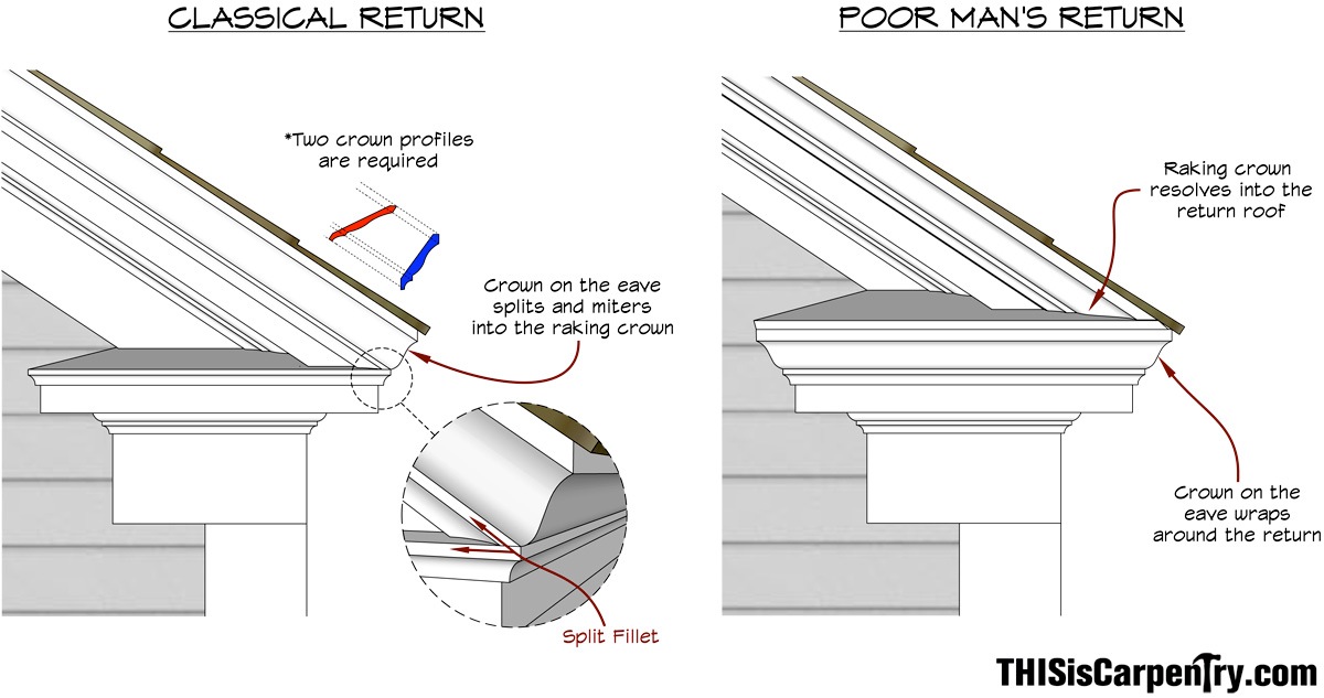
Before we get to that, let’s define the difference between two historical examples—the classical return and the poor man’s return.
Classical Returns
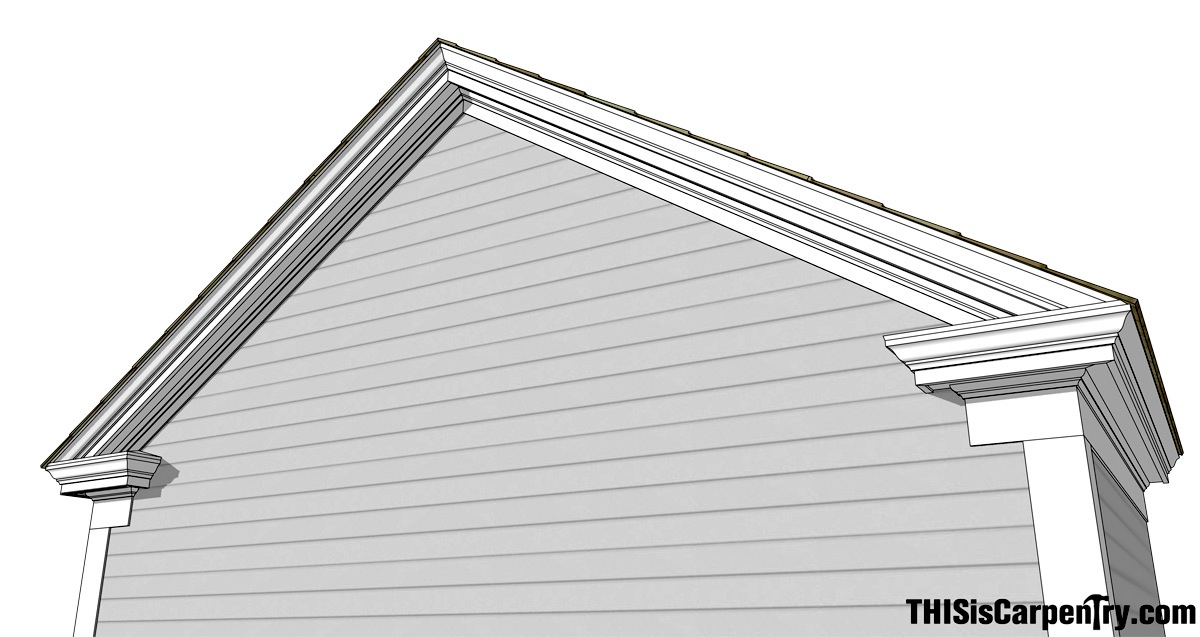
 A classical eave return is based on a pediment, like this example.
Though this a true pediment, it has the appearance of a classical eave return because the break in the horizontal entablature occurs above what would be a vertical column, and the crown molding splits at the fillet as it turns the corner. The cyma portion of the horizontal crown miters into the raking cyma, while the cove portion continues horizontality and miters around the return. This type of detail requires two separate crown profiles: one for the horizontal eave and one for the rake. While the horizontal eave crown is usually a standard profile, the required raking profile will be different for every roof pitch.
Also, notice how the projection of the soffit, measured from the nose of the cove molding to the back of the corona, are balanced perfectly—even the modillion blocks turn the corner around what would be the pilaster, so that the soffit size is exactly the same.
 |
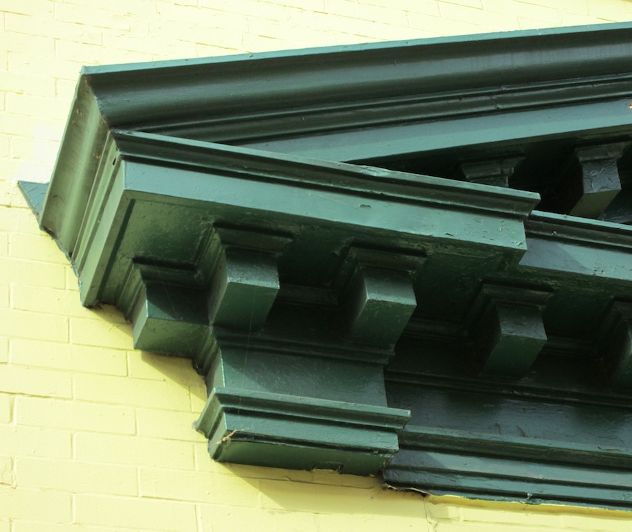
Trying to replicate this transition using only one crown profile forces the eave crown out of position. On a roof with a steep pitch, the eave crown can become almost horizontal—and this on a home in Providence, RI built in the 19th century! |
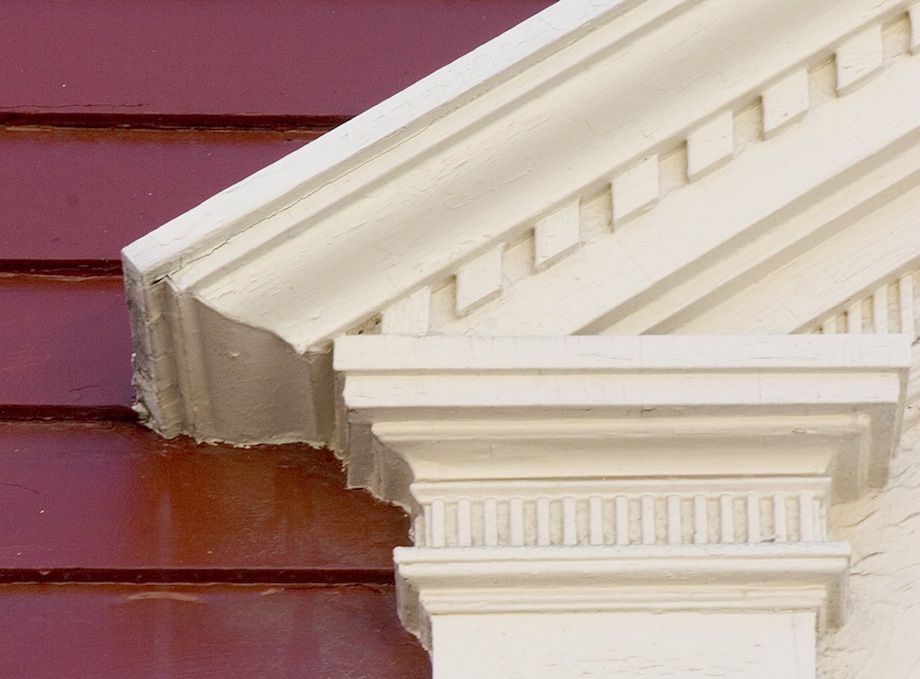
| Here’s another example, this one being an elliptical portico with coupled columns. Notice how the crown molding on the sides split and miter around the eave so that the return itself is not adorned with crown. This ‘split fillet’ is the defining detail of a classical eave return, and a classical pediment. | 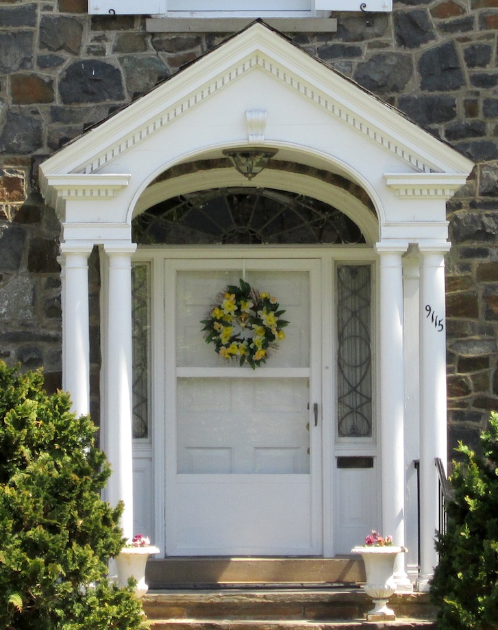 |
 |
While the eave return in this example, from Meredith, NH, uses classical details, it appears more delicate because of the deep eave overhangs. Modillion blocks are used to add visual and structural support to the extended soffit depth, which is recommended for deep soffits in GYHR on page 199. |
Not all classical eave returns were built in the Georgian or Federal styles. Many Victorian homes include them, too, like this example from Santa Cruz, CA on an Italianate home.

The design compensates for the deep eave overhang by shortening the length of the eave return roof. Though the soffit isn’t ‘balanced’ equally on both sides—the soffit on the end of the return doesn’t match the depth of the soffit on the eave—the length of the corona fits well beneath the proportion of the gable.
Poor Man’s Returns
The added cost of custom molding profiles, as well as the extra labor required for the intricate cuts involved, brought about a less expensive detail called “the poor man’s return.” This type of detail wraps the horizontal eave crown around the return and lets the raking crown simply resolve into the return roof or “cap.”
Poor man’s eave returns come in a variety of stiles.
| One good example is on Jed Dixon‘s 1860’s New England Farmhouse. As Jed says: “The poor man’s return on my home really dates from around 1816, but out here in the rural country, carpenters were a little behind the times. I’m sure the carpenter who built this return had a dog-eared and finger-stained pattern book.” | 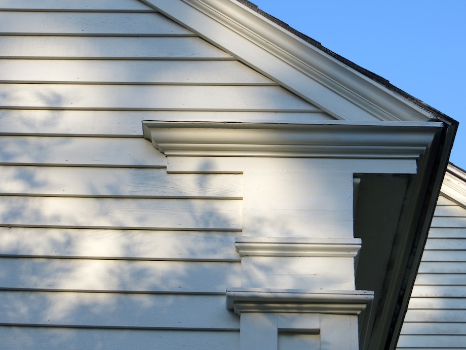 |
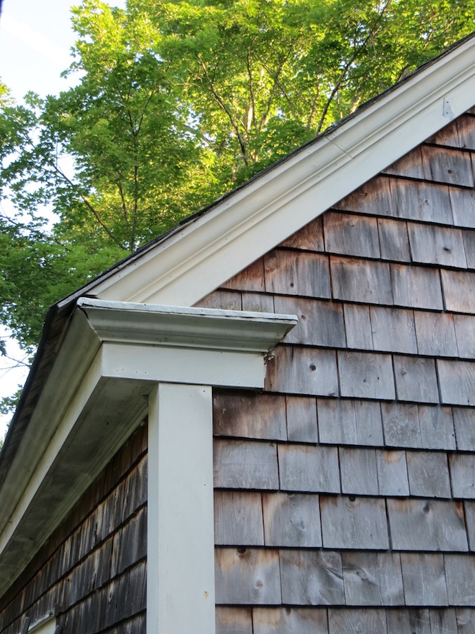 |
The returns on Jed’s home, and the returns on his shop, share a similar feature: because the gable ends have no overhang, the soffit on the eave ends before the return, which flattens the appearance of the return and increases the visual length of the corona. |
GYHR explains how important it is to use the same eave soffit depth on both the face and the end of the eave return (pg. 203), though the projection on the face can be up to 50% less than the eave. Reducing the projection to zero also reduces the classical appearance of the return.
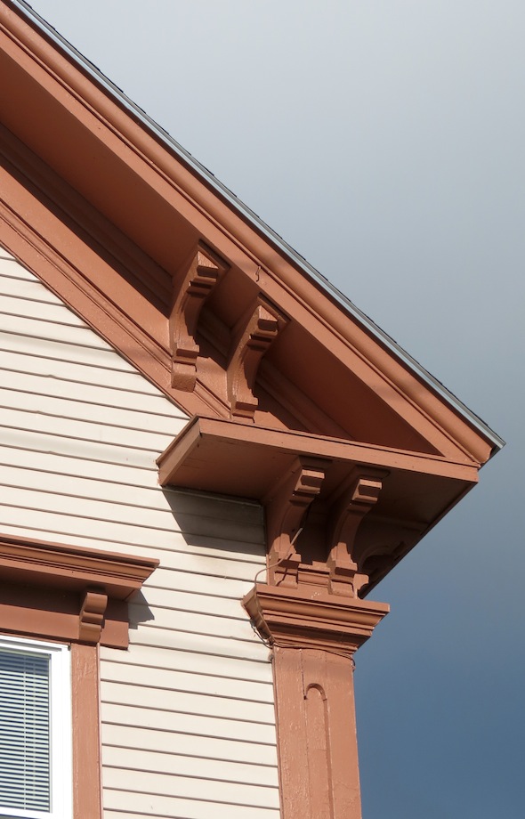
| From the opposite side of the continent, we can see an example of a Victorian poor man’s return. The same technique is used to resolve the problem of the raking cornice, but it also incorporates a decorative bargeboard and brackets. | 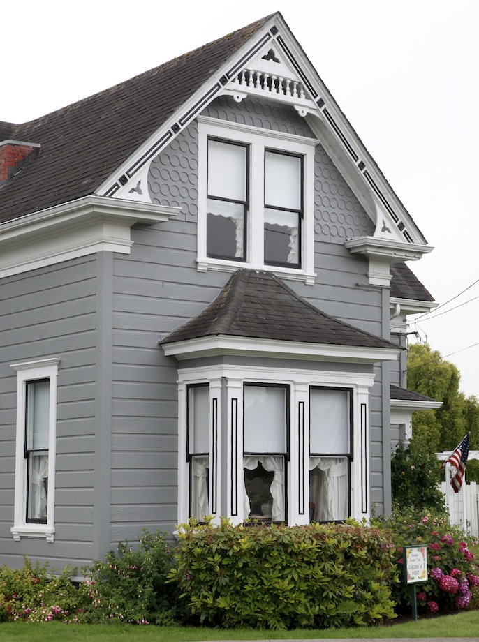 |
The Bad & The Ugly
We all know that just because something was built a hundred years ago, doesn’t mean it’s a model of perfection. Carpenters are carpenters, after all—there are good ones and there are mediocre ones.
Creating an elegant transition between an eave detail and the details on the gable end of a building really isn’t anything new. Unfortunately, the mass production of homes in this country has introduced some design shortcuts. Although we see them often, they just don’t look or feel right.
The Pork Chop
A common detail that’s seen frequently today is to simply avoid the difficult rake-to-eave transition all together by creating a triangular box on the gable end.
| This is commonly referred to as a “pork chop” return. I’ve read that this type of detail began popping up as early as 1925. It’s unfortunate to think that we may have reached a point in time where even looking back a hundred years for inspiration may lead us astray. | 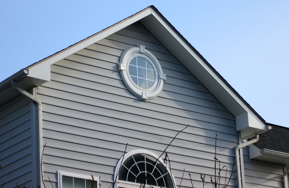 |
Steep Return Caps
The eave return roof or “cap” on most contemporary examples are often much too steep. The cornice is supposed to be the architectural detail that is highlighted—not the roof. Ideally, the cap on the return should not be visible from the ground. It’s simply there to shed water.
While commenting on this common contemporary design practice, Steven Mouzon, the author of Traditional Construction Patterns, puts it very bluntly:
…It should come to no surprise then, that the overheated, ill informed attempt at traditional design on the front wall of a ‘McMansion’ would take an element that should be invisible and morph it into a design element (pg.190).
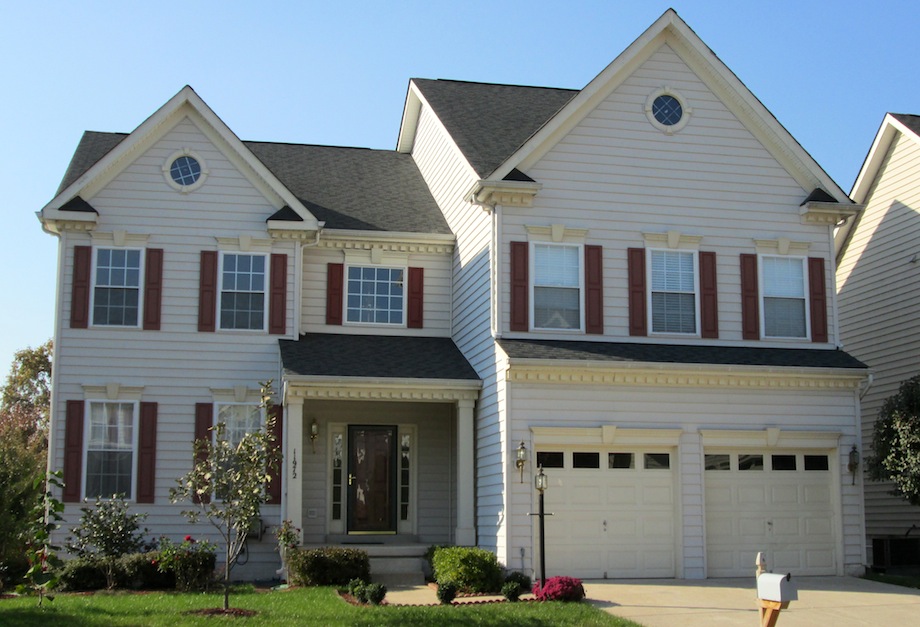
When looking at the front facade of this house, the steep dark roofs over the eave returns are the first things you notice—yet they shouldn’t be visible at all.
Proportion
The proportions of an eave detail have a major impact on how the roof visually sits on the building. It’s important to not only get the eave sized correctly for the building, but also to make sure the individual parts of the cornice are sized properly.
Without proper proportion and order, this eave return almost seems like a caricature of its historic counterparts.
Balance
The soffit depth on both sides of an eave return should normally be balanced. In most cases the corona projection on the return end should be equal to the projection of the eave. However, there are situations that may require shortening the projection on the return side, like the Italianate example we shared earlier. GYHR recommends not reducing the return projection by more than 50% (pg. 203).
| It’s not uncommon today to see eave returns that end abruptly… | 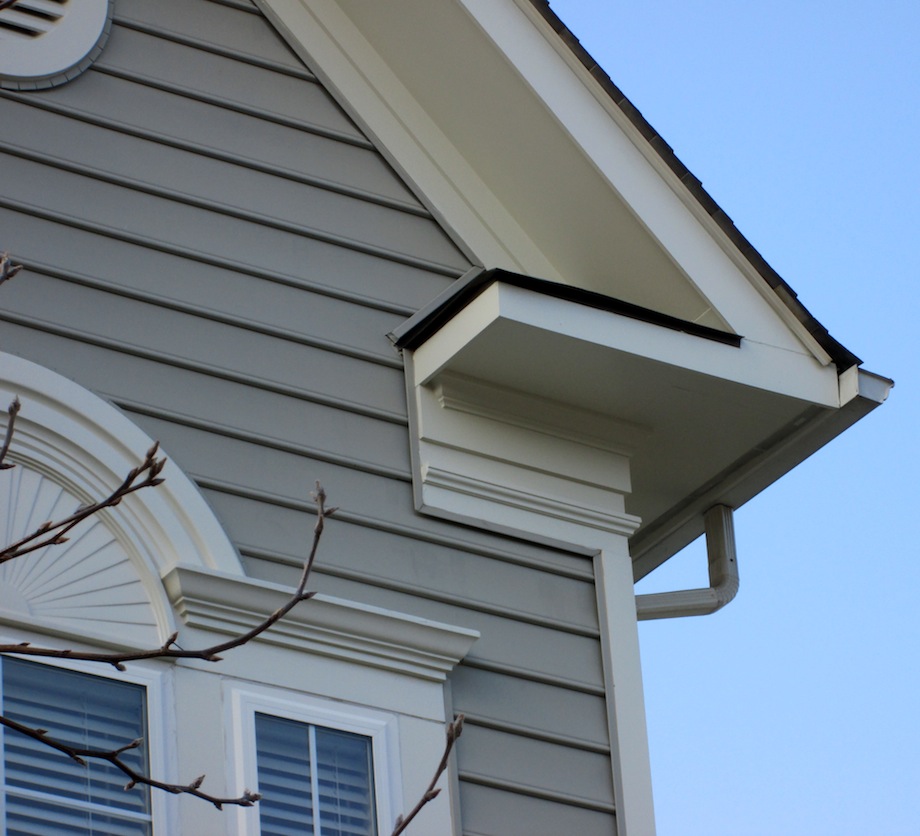 |
| …with no corona projection at all on the return side. | 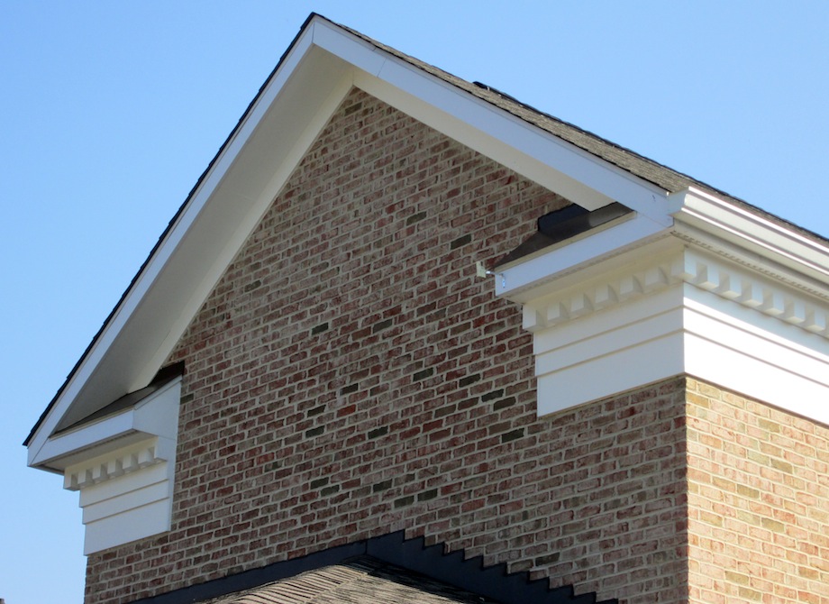 |
Interpreting Get Your House Right
Architectural design can be very creative, but some details, especially those found on classically inspired homes, don’t lend themselves very well to creative interpretation. Carpenters can avoid some embarrassing designs if they rely more on classical examples than on their own imagination. Let’s work our way through the rules and proportions in GYHR and you’ll have a whole new appreciation for the effort that goes into a successfully designed poor man’s eave return.
Cornice Height
Eave return design begins with the following simple proportion: The cornice height should be 1/15 to 1/18 the building height.
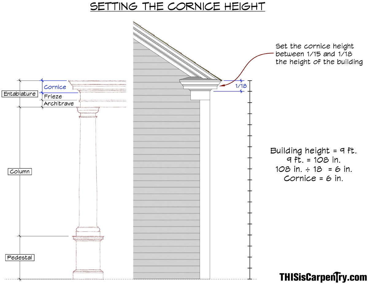
According to GYHR, the frieze is often included in that calculation on frame buildings to lighten proportions; on masonry buildings, the frieze is often omitted (pg. 201). Pay close attention to this detail because it’s the only area of ambiguity we found in GYHR, and it forms a critical part in the overall proportion.
If you include the frieze in the cornice design, as GYHR suggests, then the height of the entire entablature (frieze + cornice) will be 1/15th to 1/18th the height of the wall. If you don’t include the frieze in the cornice design, then the cornice itself becomes taller, and it projects farther. This critical judgment has a profound impact on the appearance of an eave return!
In our example we chose not to include the frieze in the cornice height because both the projection of the cornice and the height of the cornice allowed us to use standard size moldings. Plus, the end result was more pleasing, more common to what our eye expected. We used a 9-ft. building (a typical one-story), and a 1/18 ratio: 9 ft. = 108 in. 108 in. ÷ 18 = 6 in. (cornice).
Once the height is established, proportions for each individual detail—including the size of each molding and the projection—can be set.
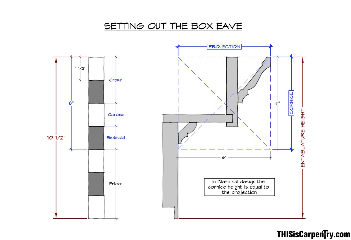
Setting out the Box Eave
GYHR includes several different box eave designs along with their proportional divisions (pg. 201, figure 10.9). The example we chose for this article was the most ornate. It includes crown and a frieze, and the proportions are determined by breaking down the entablature into seven equal parts.
The cornice has four parts and the frieze has three parts. Because the cornice height we’re using is 6 in., each part equals 1 1/2 in. Since the crown is 2 parts, it should measure 3 in.; the corona is one part, so it measures 1 1/2 in.; the bedmold, at 1 part, should also measure 1 1/2 in.; and the frieze (3 parts) measures 4 1/2 in.
Of course adjustments often need to be made, especially because of stock molding sizes. In this article, we chose to use PVC trim for the whole eave return. PVC trim is a good choice for an ornamental detail that is completely exposed to the weather, and especially for pieces that will come in direct contact with the roof surface—wood trim must not be in contact with any roof surface. Nearly all of the moldings available fit perfectly with the proportions of our seven-part cornice, except the bedmold, which doesn’t quite measure up to 1/1 2 in. in height.
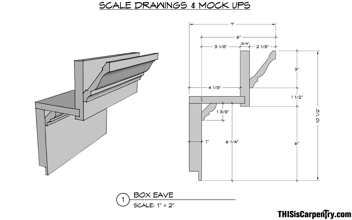
A full-scale drawing is essential for proper planning and layout. Better yet, since pencil lines sometimes vary in thickness, and moldings vary slightly in size, build a mockup using the exact moldings chosen for the job.
Eave Return Length
There are definite rules that apply to the eave return length, with the proportions determined by the length of the return frieze. According to GYHR, the frieze length should be equal to or up to 1 1/2 times the “overall height of the cornice”—which includes the entire entablature (pg. 203). That allows for some wiggle room, thankfully!
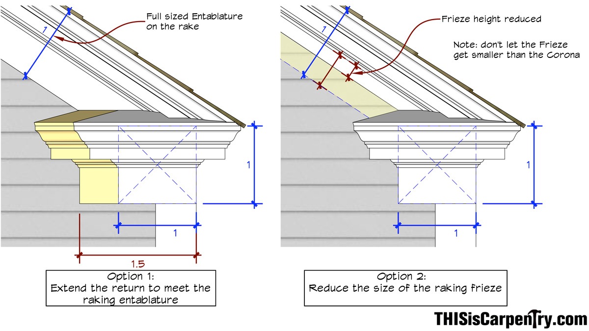
For this article, we stretched the length of the frieze to the maximum allowable dimension so that the raking frieze would resolve into the eave return roof before the hip return, which makes it much easier to cut the raking frieze!
A second option would be to adjust the size of the raking frieze to meet the peak of the return hip roof—just don’t let the frieze get smaller than the corona. In some situations it may be necessary to use a combination of extending the return length and reducing the size of the raking frieze.
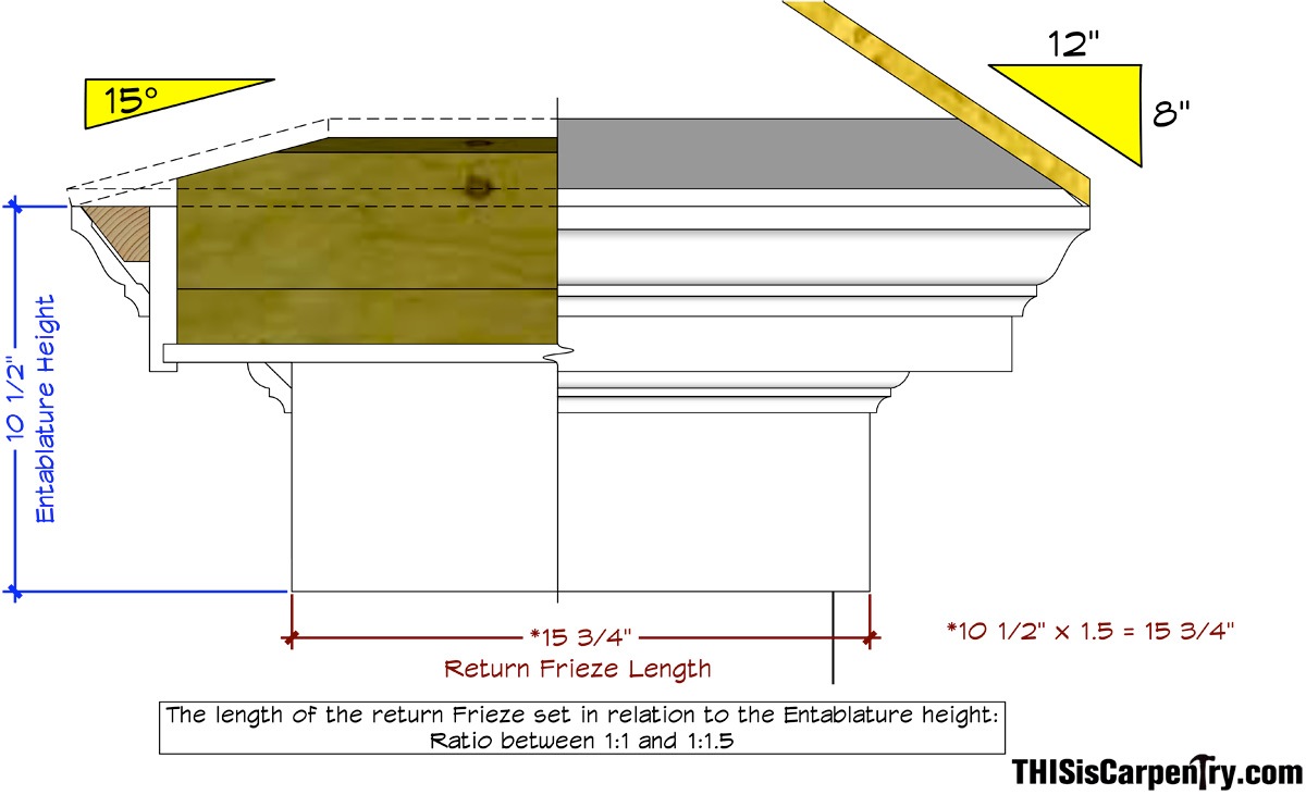
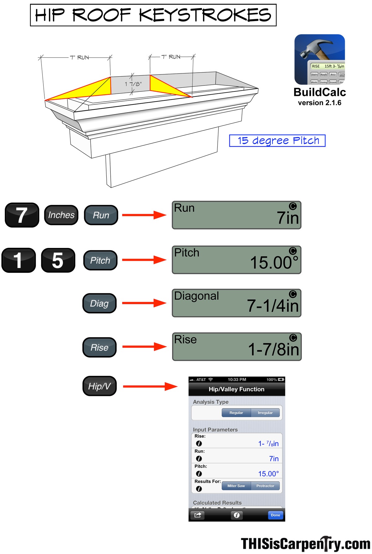
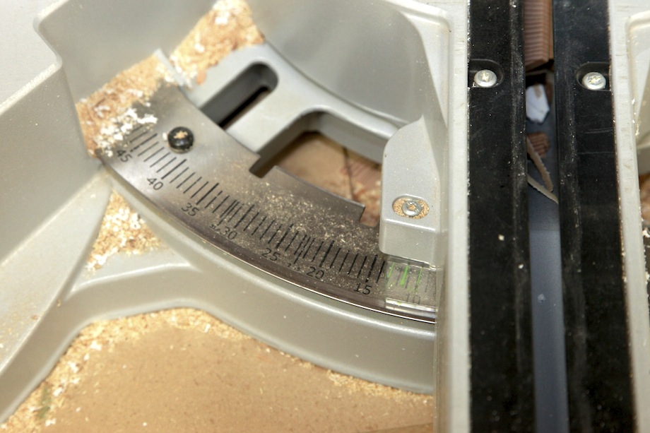
We did make one design decision based entirely on ‘finish carpentry experience’: we used a 15-degree pitch for the slope of the eave return roof. This allowed us to take advantage of the scale and detents on the saw and easily reproduce the exact angle on various components during the build. According to GYHR, the maximum pitch for the return should be a 3:12 (14.04 degrees). Increasing the pitch by less than one degree has no noticeable impact. However, this is a ‘rule’ that carpenters should remember: do not match the slope of the return to the slope of the main roof: an 8:12 pitch on a return is much too steep.
Work from the Finish Back to the Rough
As Jed Dixon is fond of saying, you always have to start with the finish and work back to the rough framing. Which means you always have to start with a good drawing (and story poles help, too!). In this case, a drawing is essential, before the roof is framed, because the rafter tails (the length of the overhang and position of the plancher cut) define the final proportions of the cornice.

If the foundation isn’t correct, the house will never be right. The same holds true for an eave return. If the roof isn’t framed correctly, the eave return can’t be designed properly. Start with the finish dimensions and work back to the framing dimensions.
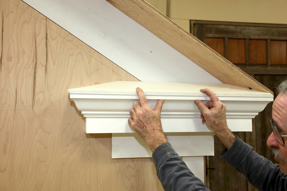
| In our example, we chose to run the roof sheathing over the eave crown because it simplified the required blocking and allowed us to use an off-the-shelf drip edge without obscuring the top of the crown. If you choose to use the more traditional layout, where the roof is in plane with the top of the crown, you will need to begin planning for it at the framing stage. | 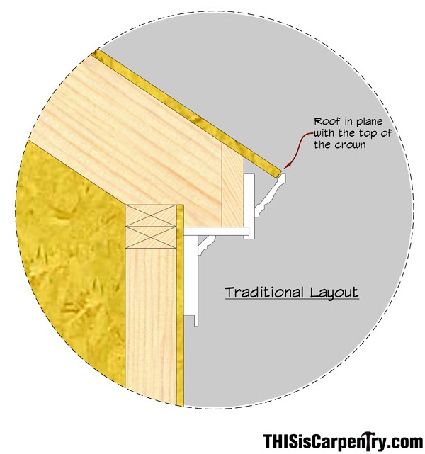 |
Construction
If the roof is framed properly, the foundation of the eave return is determined by one single backing block. We’ll call this the primary block. Cut that block precisely, and the entire job flows easily; cut that block wrong and you’ll be on a ladder with a reciprocating saw.
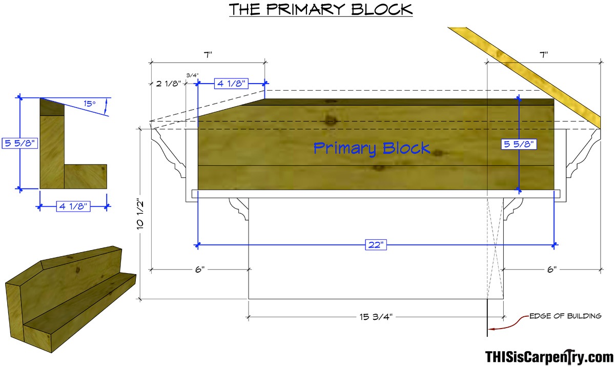
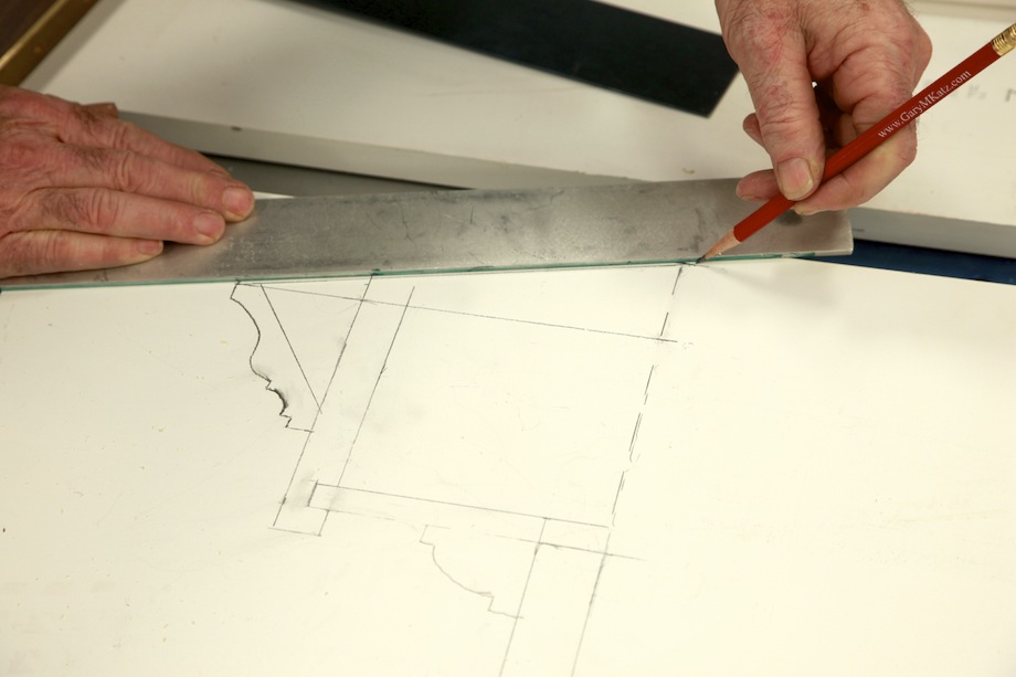
| To determine the size and shape of the primary block, I started with a full-scale drawing. | 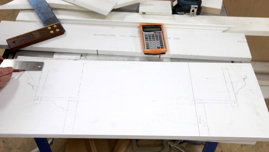 |
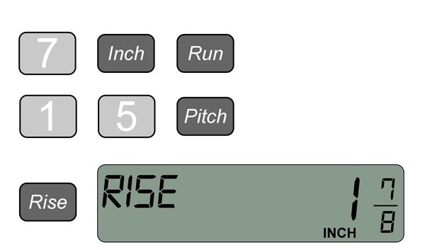 |
According to the drawing, the total run, from the tip of the crown to the peak of the hip, is 7 in. Using a construction calculator, a 7-in. run with a 15-degree pitch will have a total rise of 1 7/8 in. |
| I marked that dimension on my full-scale drawing. | 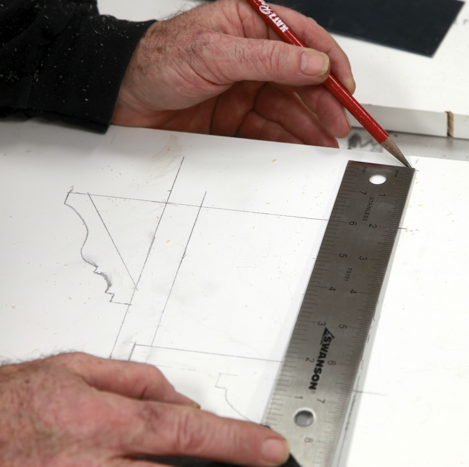 |
 |
Then I struck a line at the slope of the roof—the underside of the sheathing. |
| The green rectangle describes the exact size and shape of the primary backing block. | 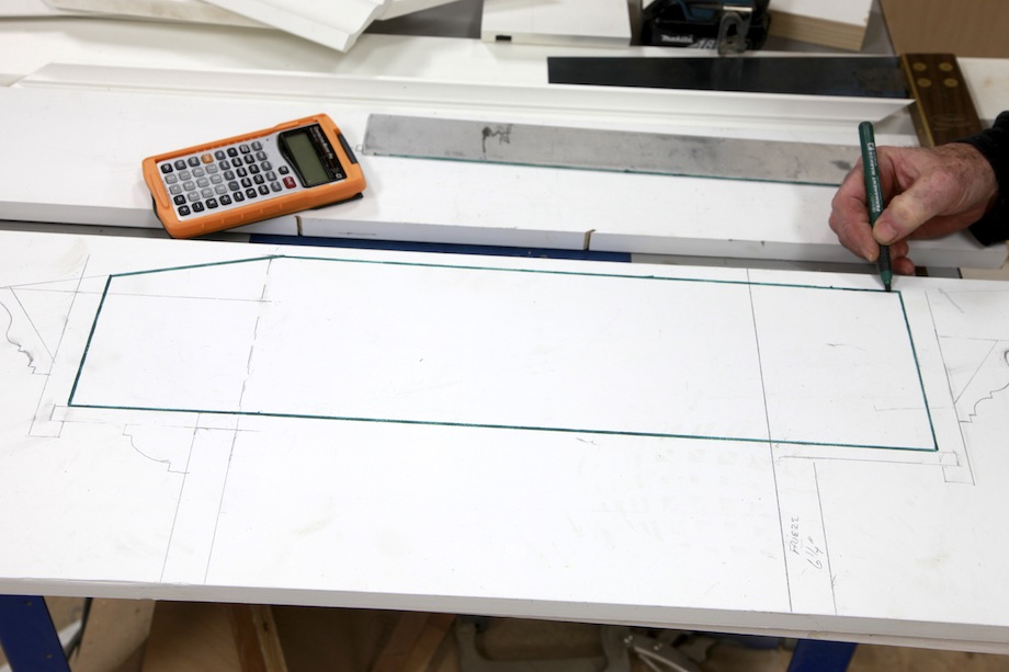 |
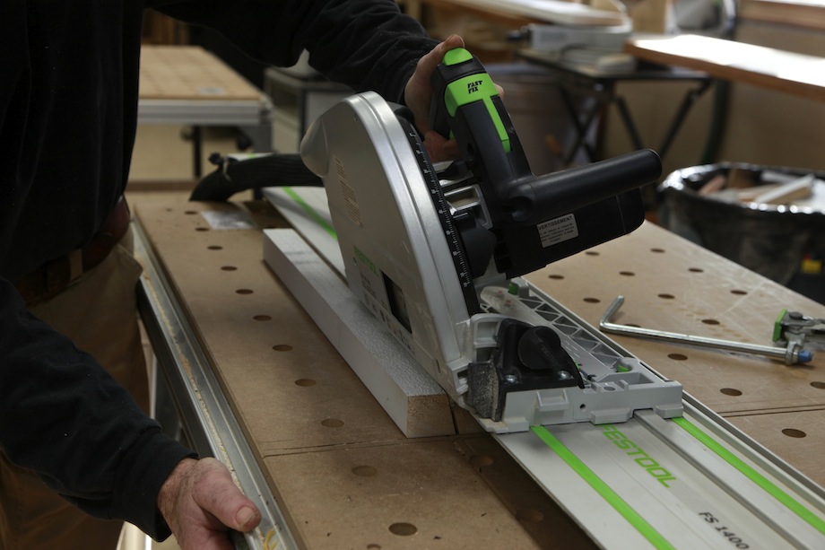 |
I cut the block to length and ripped it to width and at a 15-degree bevel. |
I laid out the 15-degree pitch using a calculator, not a protractor. If you want to control your future miter angles, do not use a protractor—they’re not accurate enough.
 |
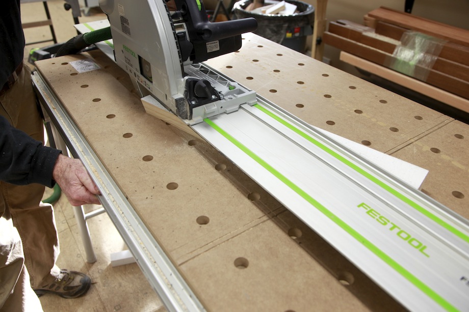 |
With a 4 1/8-in. run and a 15-degree pitch, the rise will be 1 1/8 in. I made that cut with a track saw.
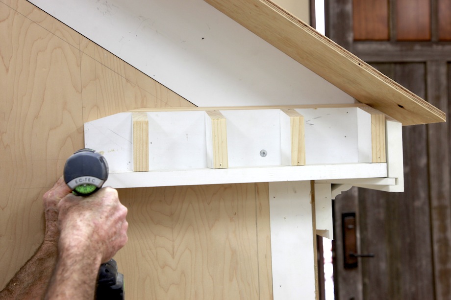 |
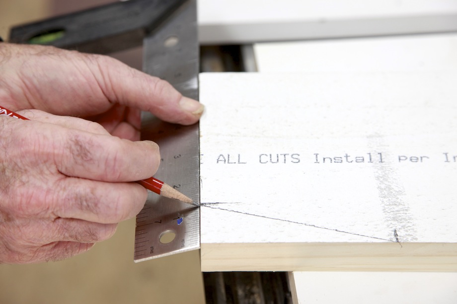
I cut small backing blocks with a 15-degree pitch and fastened those blocks to the primary block. I secured the primary block to the wall so that the bottom was flush with the level soffit cut on the rafters and the end was flush with the plumb cut on the rafters. |
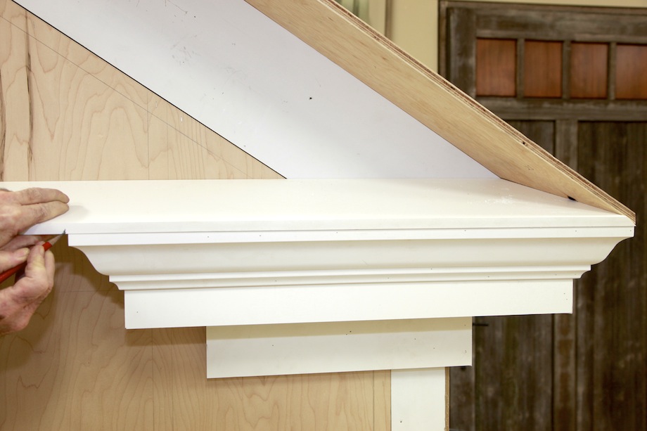
| The next steps were simple. The soffit miters around the bottom of the eave return. Because the fascia (corona) includes a groove to accept the soffit, the soffit must be cut about 1/2 in. long. | 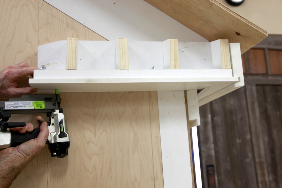 |
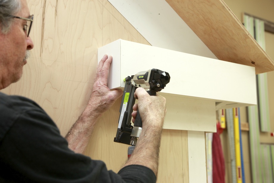 |
I installed the fascia, mitering both outside corners. These were simple cuts made on-the-flat at a miter saw. |
| I did the layout for the crown molding carefully, both at the top and the bottom of the crown. It must plane out perfectly beneath the sheathing. I used the top layout line to position solid continuous backing. | 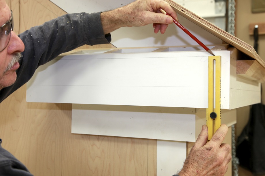 |
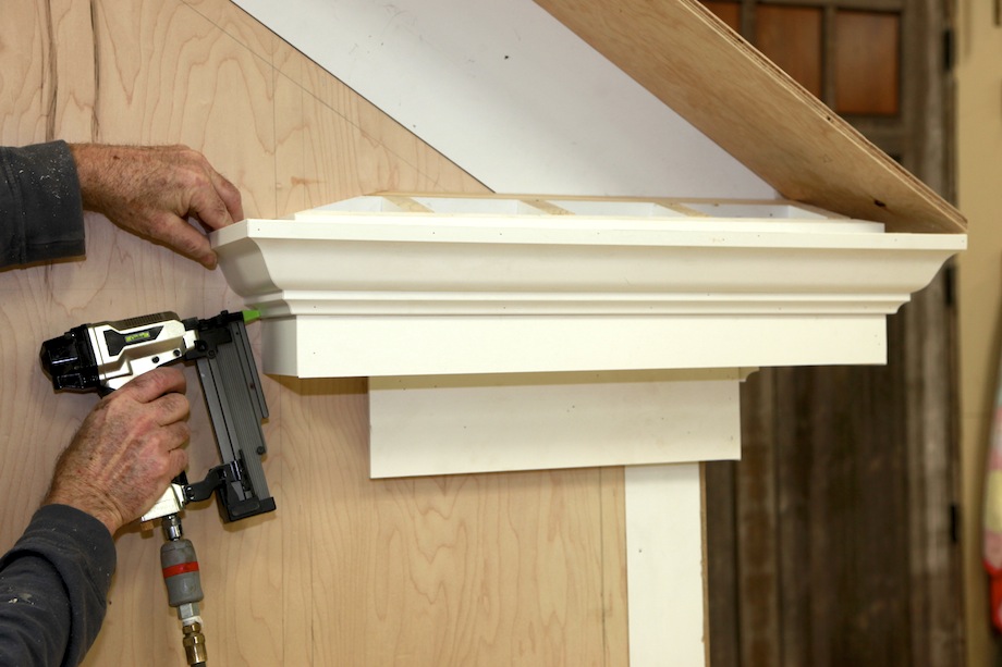 |
I installed the crown molding. The poor man’s eave return makes installing the crown easy. |
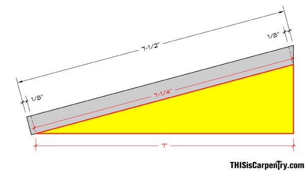
| According to our original calculations, the diagonal, or sheathing, measures 7 1/4 in. That measurement is the bottom of the sheathing—to the short point of the bevel. I added an 1/8 in. for the bevel and another 1/8 in. for a slight overhang and used a track saw to cut the 15-degree bevel at the top of the sheathing. | 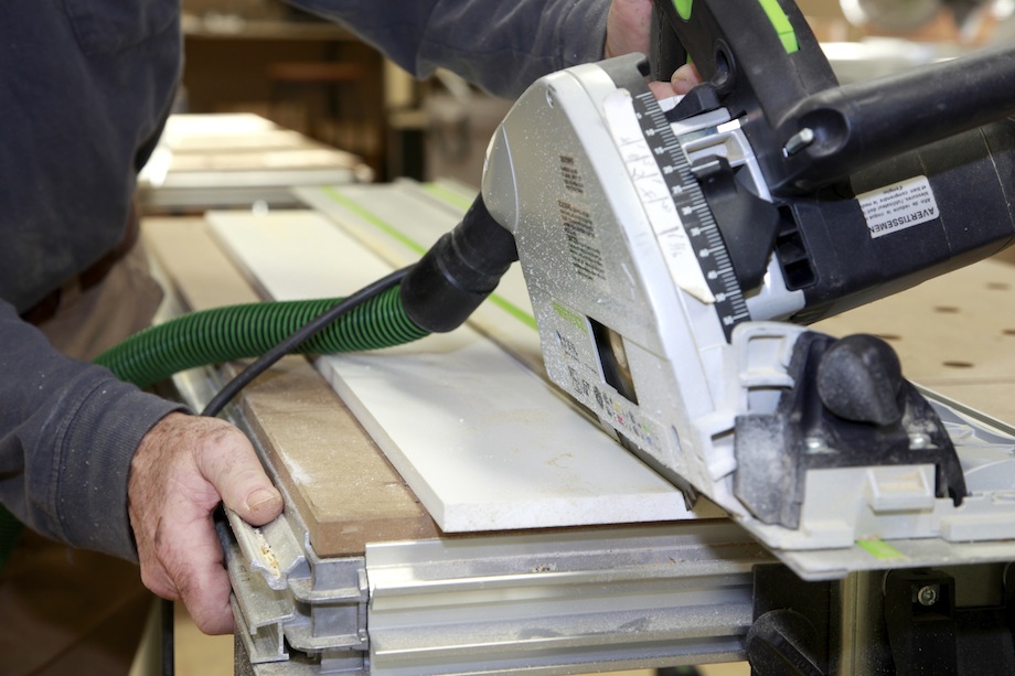 |
Construction Calculations
We used a Construction Master Pro and BuildCalc for this article. Both are handy tools, but BuildCalc also provides a digital window where all the necessary measurements and calculations can be viewed simultaneously, and it calculates advanced hip roof functions, which makes cutting the eave return sheathing much easier. Let’s walk through those calculations now, before making any cuts.
.
|
Click here to download a jobsite-friendly |
.
First, enter the run and pitch of the eave return roof. Then hit the Hip/V button and BuildCalc provides a new window with advanced features that make this job much easier.
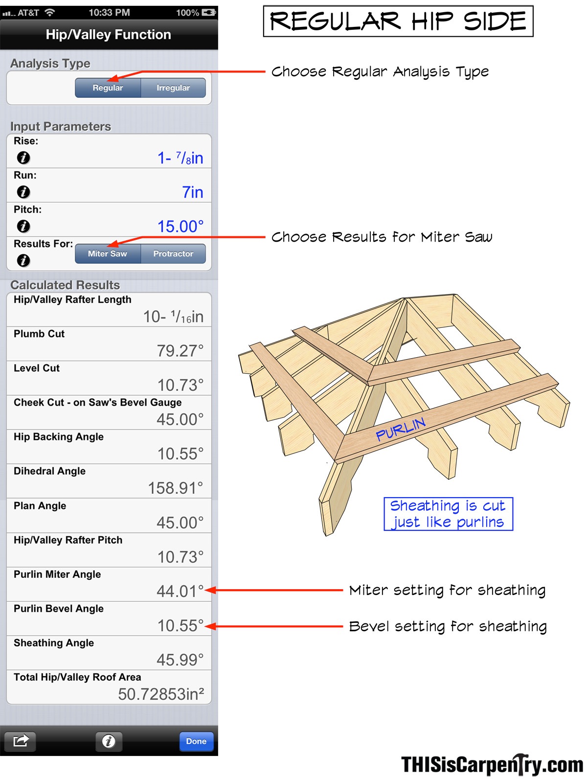
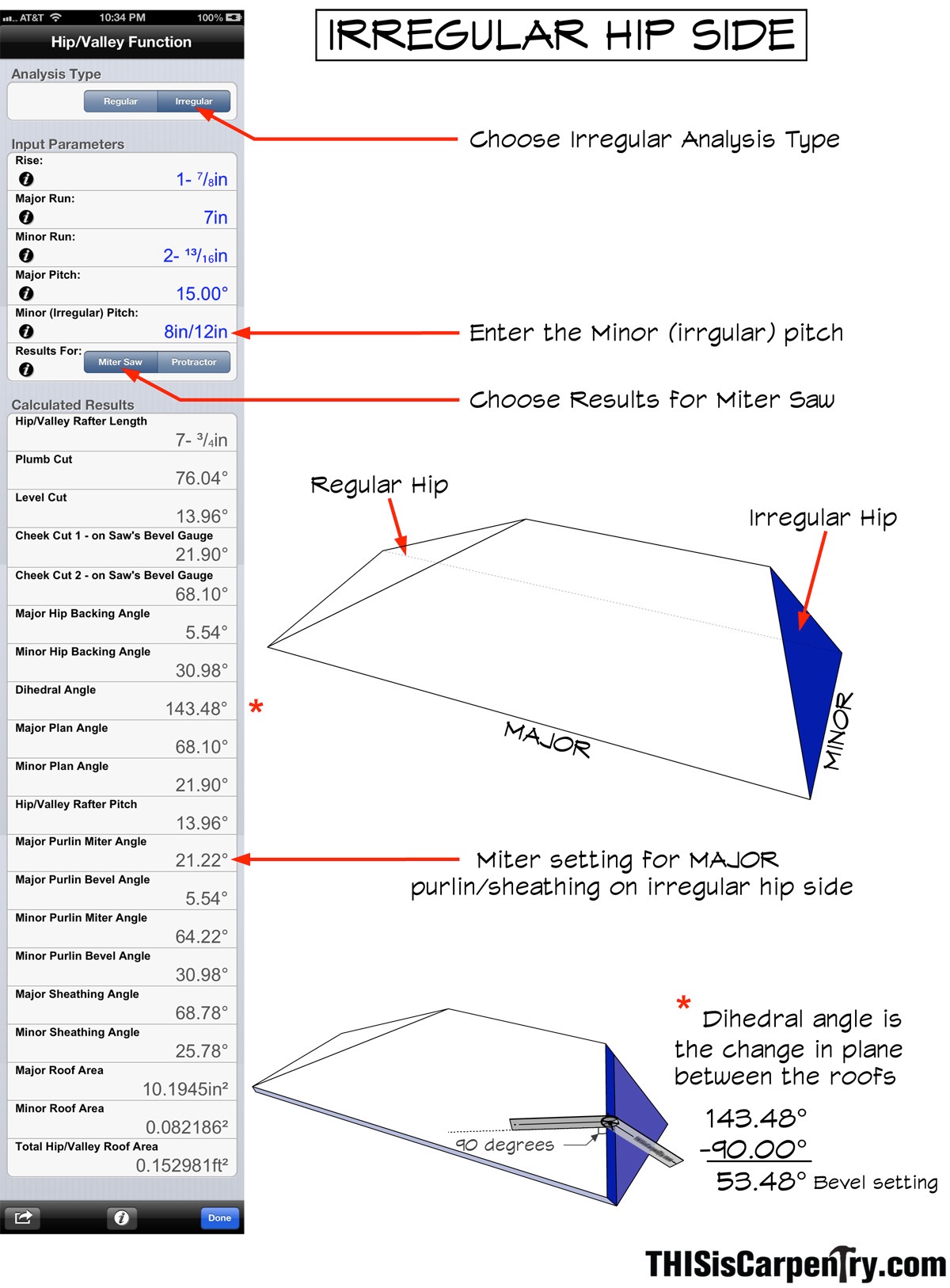
The sheathing must be cut for a regular hip on the left side, where the eave returns to the gable wall; it also must be cut for an irregular hip on the right side, where the 15-degree pitch eave return tucks under the 8/12-pitch main roof. BuildCalc displays the sheathing angles and hip backing angles required to cut the sheathing for the roof. We can save the step of converting those angles into miter saw settings for our small roof by using the purlin miter and bevel settings that are displayed.
For the regular hip side, press the Regular Button, and press the Miter Saw button. The miter and bevel settings for cutting the roof sheathing on the miter saw can be found by referring to the “Purlin” angles.
For the irregular hip, press the Irregular Button and the Miter Saw Button. You’ll also need to enter the pitch of the irregular or Minor Pitch. Remember, the eave return roof is the roof you’re really working on, so that’s the Major pitch. The miter angle for the sheathing on the right side is the Major Purlin Miter Angle: 21.22 degrees. The required bevel angle is a little more difficult to visualize since the return roof doesn’t miter into the main roof on this side—it tucks under and butts against it. The angular difference between these two roof planes is called the dihedral angle, and it is the bevel angle required for this joint.
To find the miter saw setting that corresponds to that angle we need to subtract 90°:
143.48° – 90° = 53.48°
This bevel setting is beyond the capacity of most miter saws. A few passes with a block plane or some work with a sander could tune this joint, but we cut it as steep as the saw would allow and left it. After all, this joint will be nine feet in the air and hidden by the drip edge!
 Cutting the Eave Sheathing
With the sheathing angles for both sides, it’s pretty easy to cut and even preassemble the eave return roof.
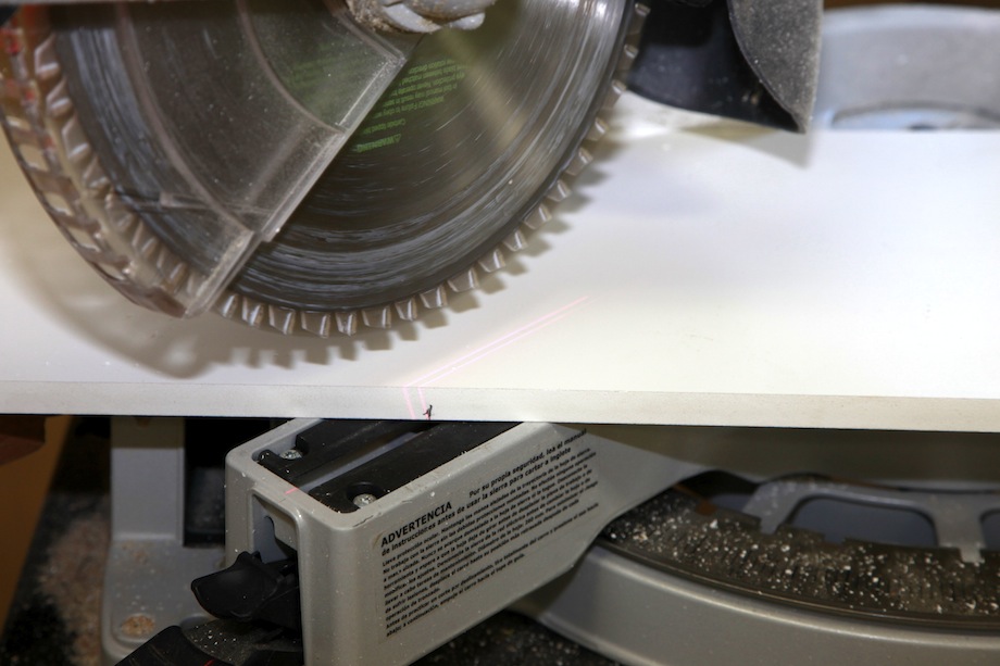
| With the 1/2-in. PVC ripped and beveled, I started by cutting the irregular side at a 21 1/2-degree miter and the maximum bevel my saw could cut. Not much of that joint is visible, so a perfect fit isn’t necessary. | 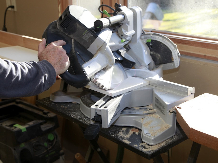 |
I checked the fit, figuring I could scribe or adjust the miter angle if necessary. But it wasn’t necessary. The miter angle was perfect. A real first for me. In the past, I’ve hunted and pecked for that angle, which is why I always start with a long piece of material.
 |
With the irregular side tight, I marked the length at the long point of the regular hip. |
Years of cutting crown molding have taught me to always cut the self-return cap first—which is really what the hip return is—otherwise, the piece might be too short to hold safely in the saw.
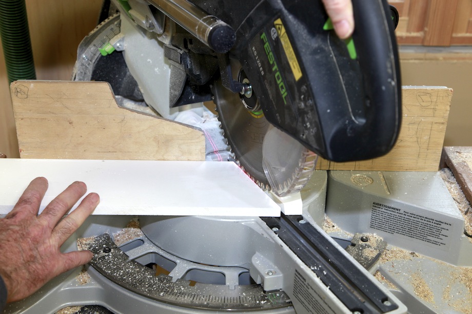
| The short return piece is simply cut so that the miter daylights out to zero. | 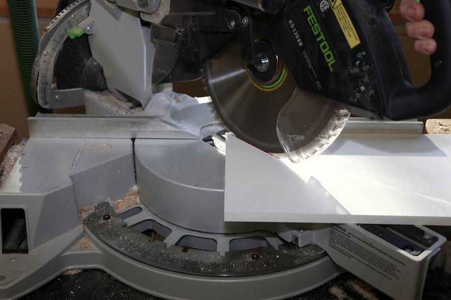 |
Then I swung the saw and cut to my measurement mark—the long point of the miter at the short point of the bevel:
 |
The long point of the miter because I marked the board at the crown molding, not the wall; the short point of the bevel because I marked the board on the bottom of the sheathing. |
I preassembled the PVC sheathing using 2P-10 glue, the same way I preassemble everything for a presentation/demonstration. If I were working in the field, I’d use PVC cement or Bond-and-Fill.
| After the glue set, I scraped off the excess. | 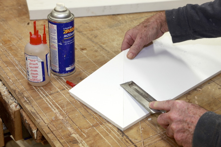 |
The sheathing fit perfectly the first time. As Mike Sloggatt likes to say, “Always trust the math—it’s never wrong unless you enter the wrong numbers.”
Cutting the Raking Cornice
Cutting rake angle miters might confuse you, but keep your eye on the prize—don’t be distracted by something that seems hard and isn’t.
All of the rake angle moldings are exactly that: moldings that are attached at the angle of an 8/12 raked roof, which has a 33.69 pitch. That means they must be cut with a 33.69-degree miter angle at the eave return roof. You can’t cut that angle on a miter saw. The saw won’t swing far enough to create such a sharp angle between the blade and the fence.
So you have to use an acute angle jig.
| With a 45-degree jig as the new fence, every degree you swing the saw toward the jig is like subtracting one degree from 45 degrees. | 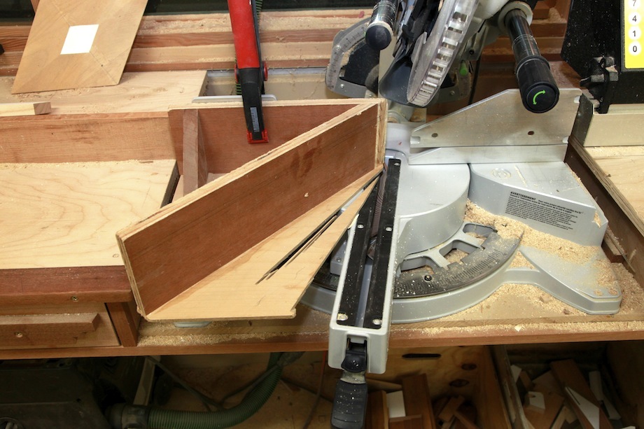 |
 |
So swing the saw to 11.31 and you’ll be cutting a 33.69 angle. |
| And don’t forget to tilt the bevel to 15 degrees for the slope of the eave roof! | 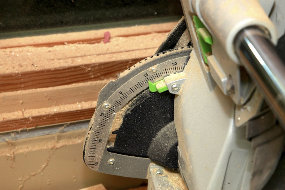 |
Cutting molding on a miter saw can be confusing, especially on a raking gable. Not only do you need to know which direction to swing the miter and which direction to tilt the bevel, but you also have to figure out the right position in which to hold the molding.
For that reason, I always remind myself to identify which part of the saw represents what. For instance, when you’re cutting baseboard standing up at your saw, the fence represents the wall and the base of the saw represents the floor. But when you’re cutting baseboard that runs down a stair way (and looks terrible! but that’s another story), the baseboard must lie flat against the base of the saw, in which case the base of the saw represents the wall.
Rake moldings are exactly the same. Sometimes the base of the saw is the wall and sometimes the fence is the wall, all dependent on the position in which you hold the moldings.
| You have to stand the soffit up flat against the fence (if your saw can cut that tall). | 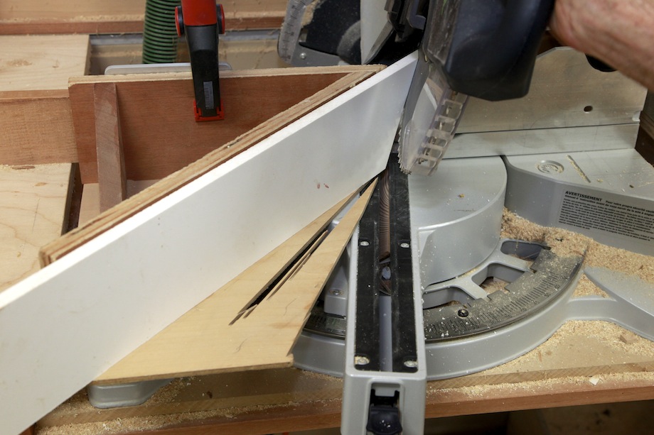 |
 |
You can also lay that material flat on the saw and cut it at a 25.78-degree angle—that’s the “Minor Sheathing Angle.” |
Cut the corona and frieze lying flat against the base of the saw (the base of the saw represents the wall); cut the bedmold and crown nested against the fence and saw base, but remember, when cutting rake moldings, stand the molding right-side up and tilted back against the fence (the base of the saw represents the wall, the fence represents the underside of the roof).
| First I installed backing for the raking cornice. The dimension of the soffit backing is identical to the depth and projection of the eave cornice. | 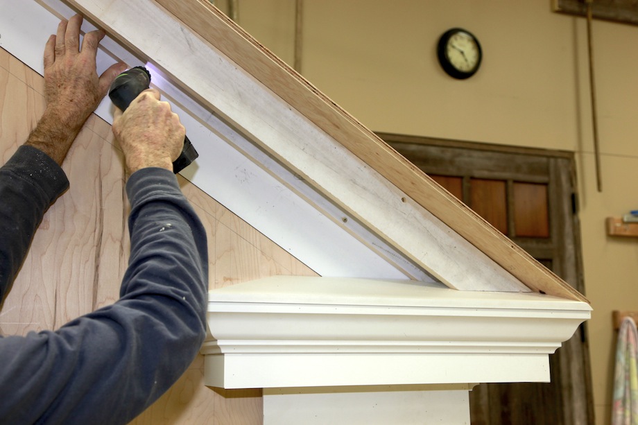 |
| Next, I tacked on the soffit board… | 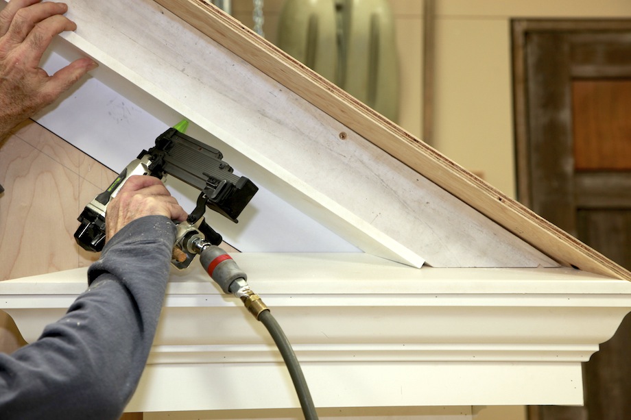 |
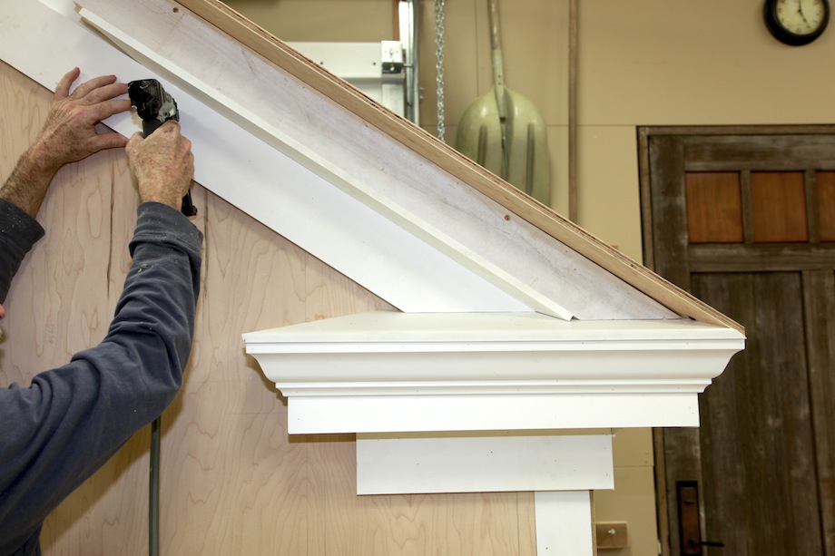 |
then the frieze… |
| then the corona… | 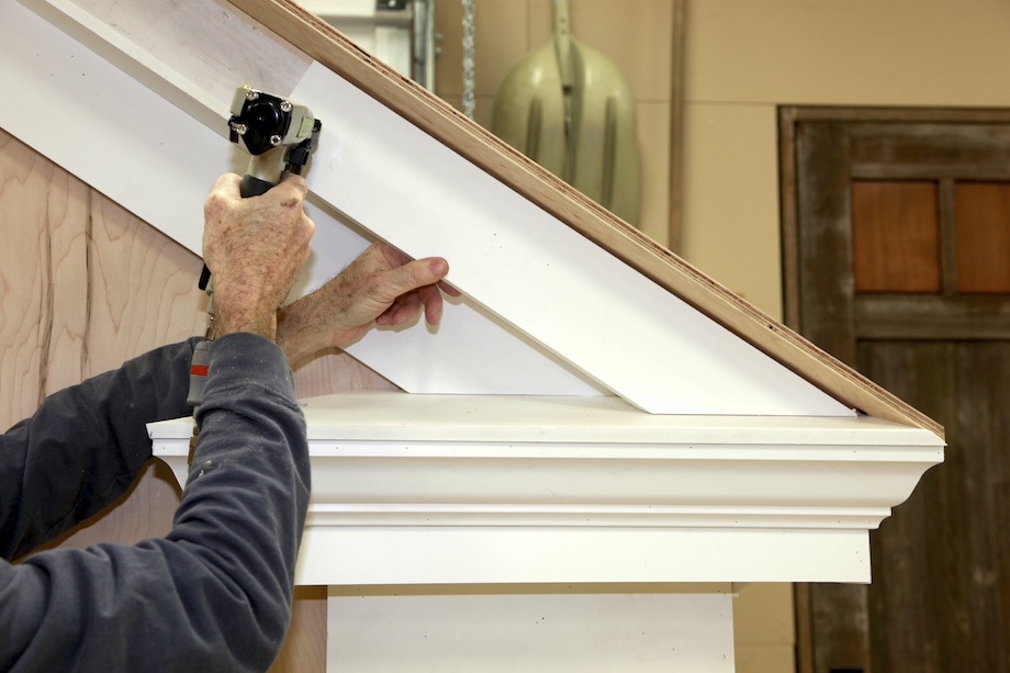 |
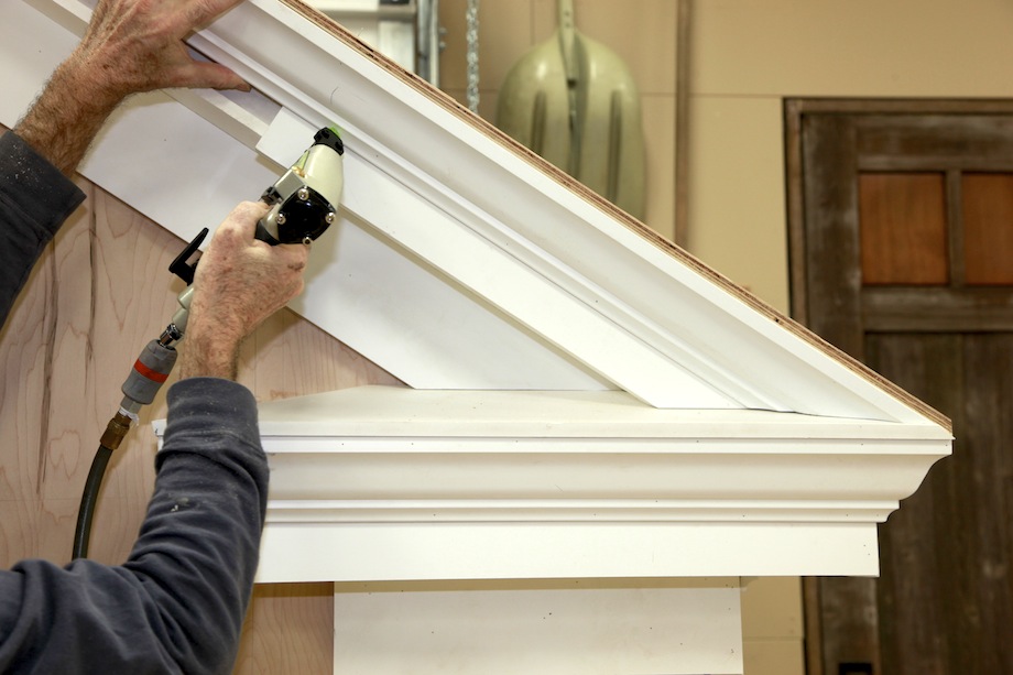 |
then the crown… |
| …and finally the bedmold. | 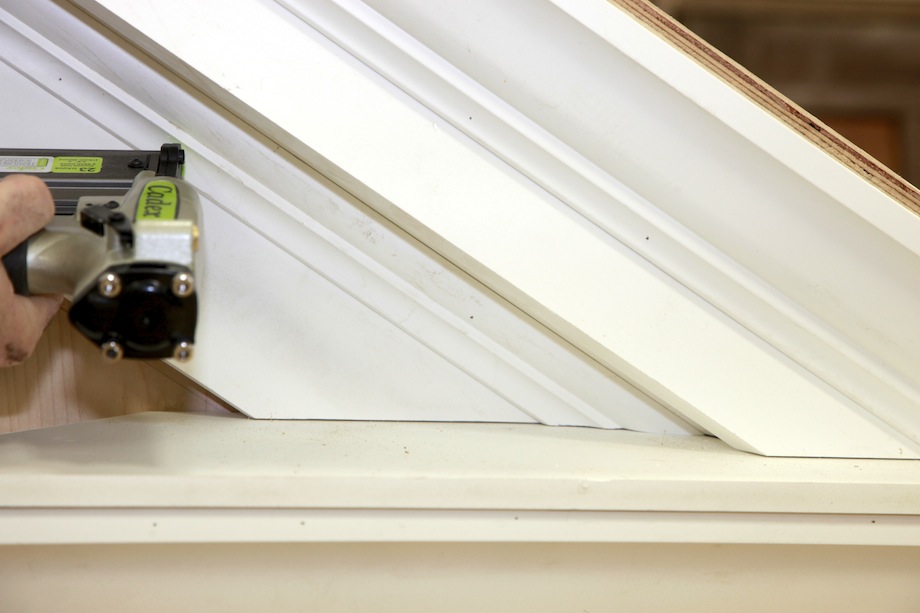 |
Those of you paying close attention will have noticed that this article doesn’t include flashing! Obviously, even though the eave is made entirely from PVC, flashing would still be required from the sidewall to the eave roof. But with so many creative carpenter/readers around, I’m sure we’ll get plenty of comments about how to flash an eave roof properly.
One last word, both about eave returns and about the purpose of THISisCarpentry: This type of return doesn’t go with every architectural style. Know the style you’re working with, as Stephen Mouzon writes in Traditional Construction Patterns:
Buildings that speak an existing architectural language should take great care to follow the prescribed eave proportions of that language. In other words, be fluent in whatever language you choose (pg. 200).
Bravo Gentlemen! Only wished you would have been two months earlier. I had to use Gary’s Egyptian method to figure the details on a rooflet from an 1829 house. I used GYHR extensively but as you mention, I needed Paul Harvey to give me the rest of the story. Now I have the details and can go back and understand how I should have done it right the first time. Thanks for incorporating the take aways for field use. I need to get an iPad w more memory.
Merry Christmas to a all at TIC! See you in RI in the spring.
Please keep up the excellent work.
Kirby,
Thanks for the comment! It was a fun exercise for us and we learned a lot in the process.
I also want to pass along a note from the developer of BuildCalc. A new version was released on Friday and it has a small bug. If you are upgrading from a previous version you may not be able to bring up some of the advanced functions and preferences. The fix right now is to delete the app and then re-install. It worked for me.
Todd
This was a most interesting article.
At the beginning, I was befuddled because I didn’t know what features all those high-falutin names referred to.
Would have helped to have a diagram with arrows pointing to those features with their names.
I realize this is a difficult subject to describe in a written article.
Seeing and doing is so much easier to understand.
Reminds me of trying to describe a spiral stair without moving your hands.
Enjoyed the article. It’s sad to see the old style craftsmanship go by the wayside.
Jim,
I’m glad you liked the article, but I feel bad that you had a hard time with it. I think that we may have jumped into some architectural terms too quickly. Thanks for your input!
We are going to add a link to Brent Hull’s article on entablatures to the beginning of this article. It is a great article that covers the all anatomy and terms in detail.
Thanks again,
Todd
Excellent article!…based on an excellent reference book(GYHR) that every good builder owes it to themselves to own and revisit regularly. I like the fact that you mention poorly properly proportioned eaves just don’t “feel” right. Indeed, I believe architecture has the responsibility to deliver to us not only utility & comfort, but also visual pleasure.
While reading this article I couldn’t help but think the modern & ubiquitous “K” style aluminum gutter has vastly contributed to the lost art of constructing classically proportioned eave details. I makes me wonder how do we best incorporate modern gutters (and downspouts) into these classical details???
Sonny,
If you have the GYHR book, I believe you’ll find a paragraph or 2 on page 209 about “Built in Gutters” which I think was meant to show how we can incorporate the OGEE gutters that so many refer to as “K” style.
My approach is not to leave the aluminum gutter face showing as depicted in the book, but rather to put a real piece of molding up to hide the aluminum from sight.
I know Mr. Murdock says no wood should ever be put in contact with the roof and for good reason, but I prefer NOT to see PVC or Aluminum on the outside of MY house anywhere.
Ken,
You beat me to it! Yes, GYHR shows a detail on page 206 for built in gutters. I like your idea of concealing the aluminum gutter with trim too. Thanks!
As far as not allowing wood to contact the roof surface, we were referring to the raking trim. In our example we ran the trim down the rake and tight to the return roof. Most wood trim manufactures recommend a 1 in. clearance from roofing material and WindsorONE even recommends 2 in.
Todd
Great article guys! I’ve always felt like I’ve been winging it when it came to returns. This article confirmed that… What you describe as the Poor Man’s Return has been my mainstay.
It’s topics like this that remind how much more there is to learn.
Thanks for publishing,
Greg Callow
Excellent article ! I don’t install eave returns very often, but every time I do, I wing it. It feels as if I’m recreating the wheel each time. Now, thanks to this great article, I can proceed with confidence. What you call the poor man’s return has also been my mainstay.
The last time I installed returns (I had to make four of them), I stumbled on to a useful time saving technique. With a helper on the ground making the cuts, I did a test fit of each piece, confirming the fit. Before installing, I had my helper cut three more and group the pieces in sets. The remaining three returns went up quickly.
Thanks so much for this thorough and immensely useful article.
Harvey,
Great to hear from you and thanks for the kind comments! I’m glad you liked the article. GYHR is a book worth owning.
Todd
PS The new version of BuildCalc includes the adjustable “starting” and “ending” members option in the baluster function. I know we were talking about that when we published you wainscoting article. I’ve played with it and it works great!
I wish there were more articles like this these days, or at least more pattern books on jobsites. Coincidentally I was just on the Azek website this morning and saw a gallery post of some exterior trim that really missed the mark in terms of understanding the proportions and relationship between pieces.
Thanks for helping to keep traditional design alive, Gary and Todd.
Todd, What a great article! You really opened my eyes about something I thought I understood and I’ve been building for years.
And I love the way you take it carefully through each step so we don’t have to fake it and reinvent the wheel each time we build one of these things.
Around here the “Poor man” is just called an eave return even though it’s really a degenerate version of the classical return. The unsophisticated rural carpenters of the 17 and 18 hundreds used it and left the classical returns to the city guys. Sorry to say, even the city architects today can hardly get a poor man right.
I knew that the classical return needed a rake version of the crown but I never understood that cove or lower ogee of the crown splits and follows the facia around the return, or that the soffit board should miter around the return and make the overhang equal on the eaves and gable ends.
I’m happy when you and Gary use the classical terms for the parts of trim details: corona, frieze, entablature and all that. It won’t do us any harm to learn more about what we’re doing. It makes me think that I’d like to see a couple more articles come out of this: one on the basics of classical architecture and how it applies to what we design and install, and one on rake moldings.
Jed,
Thanks for the kind words! It really means a lot to me coming from you. Gary deserves a lot of the credit too. It was a team effort and wouldn’t have been possible without him.
I’d love to see a TiC article on raking moldings too! I have some ideas…
Happy Holidays,
Todd
Awesome article! (And one that I wish I had when I built my Georgian colonial with full gable pediments three years ago.) Now to take it a step further: for the purists like me, what size crown profiles are needed with different roof pitches? Is there a table or book with these?
Pete
Pete,
Thanks, I’m glad you liked the article. The profile for the raking cyma is not just a larger size of the eave crown, but actually an elongated version of it. Traditionally it is developed by using a full scale drawing to project points along the eave profile at the required raking angle. GYHR touches on the subject briefly on page 85 (fig. 4.19.) You can find more information on the technique in older pattern books and even on the internet by searching for “raking cyma.” It’s also possible to develop the required shape by using SketchUp
Some broken pediments even use three profiles. A third even larger profile is used for the top return. You can spot those by looking for plumb fillets at the top return.
Todd
Jed;
Your comment about eave returns in your area got me thinking. While driving around in my area, I looked at eave returns. Both types, the classical and poor man’s returns are well represented. I was surprised to find the classical return is more common. There are a lot of very old houses in my area. The newer houses here (the one’s that are trying to look like old houses) feature poor man’s returns. No surprise there.
Pete;
When I first started in the trades, my local lumber yard sold “rake crown”. Although I never used it, my understanding is that it was used (on the rake) for a classical return. The standard crown was used on the horizontal runs. I was told it was a perfect fit for an 8/12 pitch. I guess you would have to “fake it” for other pitches ?
I once saw a description, in a book, on how to use a pair of dividers to draw out the profile for rake crown, based on the desired roof pitch ! I guess the carpenter would then get out his molding planes and make the crown !
Justin;
I have used Kleer pvc trim quite a bit in the last two years. Their selection of moldings is a little bit better than Azek. I have been able to put together a reasonable, somewhat traditional looking, door and window casing with their moldings.
I have been struggling with returns for a Greek Revival Reproduction. I was literally transferring dimensions from a hard copy of GYHR and decided to a google image search. Up came this article. Perfect. Thanks so much!
Great article. I was wondering about the measurement of the crown. I get where the 3″ comes from but struggling to understand where the 2 1/8 run comes from? Is the crown perpendicular to the roof? I thought I read somewhere that it should be at 45 degrees.
Thanks,
Seth
Hi Seth,
Thanks for the comment, and sorry for the late response!
The 2-1/8 in. measurement was taken directly from the crown molding being used in this example. It was installed ‘in position’ on the corona/fascia so that it’s top edge intersected with the roof sheathing.
Since crown molding has a ‘spring angle,’ there are two different measurements for each crown profile–the drop (or height) and the projection. While the 45° spring angle you mentioned is common, this molding has a 38° spring angle, which is more typical.
Classical proportions are normally based on the vertical height of each molding when installed. Choosing the correct crown molding size out of a catalog, or from the bin at your local home center or lumber yard can be difficult. This is because the dimensions that are often used to describe the molding are it’s total width and thickness–for example: 3 5/8″ x 9/16″. These given dimensions have absolutely NOTHING to do with how moldings were historically sized. You need to find the actual drop/height of the molding in order to incorporate it proportionally into any classically inspired design.
Todd
Gary and Wm. Todd –
Bravo – much respect. You have created a treatise – an authoritative resource – for the correct how and why of eaves returns. This is the sort of thing that has been absolutely lost in production homes at all price points, and sadly, most of the custom work today also misses the mark, thanks to incorrectly proportioned pre-fabricated details that are widely in-use, and a general lack of knowledge among both building designers and finish carpenters. It’s not that they (actually ‘we’ – I’m also guilty) wouldn’t design/build them correctly if they (we) knew how – the information is just not that easy to come by.
The other place you’ll never see these details done correctly – Modular housing. We have a ton of modular home plants near me, churning out some of the ugliest and most poorly-detailed housing you’ll ever see.
It’s such a shame, because factory-built housing SHOULD produce the opposite – a superior product at a more competitive price. Warm happy workmen, controlled conditions, bring the work to the worker, etc etc. Everything “Lean”. Unfortunately that’s not the reality, and it’s largely because of a complete lack of knowledge in the design phases. A few years ago I toured a bunch of the larger plants in central PA, and there was not one single architect or professional building designer employed by any of them. Plans were “drawn up” by CAD drafters with good CAD knowledge but limited background in traditional architecture. So you get “pork chops” , McMansion returns, or pre-made foam details where one size fits all. Not to mention the circle-top windows tossed in everywhere for no reason, “stone” work that starts in mid-air, crown mouldings installed upside down throughout (not kidding), and so forth. The typical buyer has no clue anything is amiss, but the end result are homes that scream “Modular” a mile away.
I’m sure this piece will have some influence for the better. In fact it already has for me, I’m going to start putting your information to use immediately -I’m starting a traditional design for my daughter and her husband – the proportions will be correct !
– JLS
Todd (and Gary)
Thank you so much for this article! I’m getting to comment a little late but I just had the time to really re-read it carefully and refer back to my dog eared copy of GYHR. I’ll just echo other commenters in saying how important this subject is for our trade, and commend you for really bringing these traditional design and building methods to life using sketch up and other modern tools.
I’m especially thankful for showing how to use buildcalc to find those agles. I’ve been using that app for a while but I’ve never fully explored that hip valley function. It just never clicked in my head what a purlin miter/ bevel angle really meant! And the dihedral angel?!? Who knew… Just amazing. Now I know.
One question: where did you find in GYHR that the cornice is divided into 7 parts? You say it’s pg. 201, figure 10.9 but I don’t see it there. There are some cornice proportions to be found in the section on entablatures (pg 55) and elsewhere but I can’t find where it it is 7 parts; actually most of the proportion seems to be based proportionally on the diameter of the column. While I get this if you are using classical columns and a full entablature it seems more ambiguous when your just looking at the roof cornice. Where do you start? The corner board size would seem to relate here too…..I really like your method of dividing into 7 parts. It’s clear and easily understandable. Just trying to find the reasoning behind it and wondering if there might be other situations where you would use different proportions?
Thanks again for the great article and all the great work you do for TiC.
Rob
Rob,
Thanks for the comment and kind words! The proportional divisions of the cornice aren’t specifically mentioned in the text, but are implied by the rectangular “story poles” next to each example in illustration 10.9. You will also see this technique used in older pattern books to show ratios.
The examples the author shares in that section are generic and don’t fit exactly into any specific order. If you had a specific order that was used on the rest of the home’s exterior millwork it would probably be best to repeat it in the cornice. As far as where to start—start with the height of the building and work backwards from there. The diameters (top and bottom) of a classical column are derived proportionally from its height. The ratios are different for the different orders. To add even more confusion to the subject, the orders are often ‘attenuated’ (GYHR pg. 144).
I don’t believe the size of a simple corner board would come into play here, but it certainly would for sizing pilasters.
Todd
Todd,
Thanks for replying! Yes of course, I see those divisions next to the drawing now that you point them out. Thank you. I understand now.
I agree that you wouldn’t size your cornice from a simple corner board. I guess I was thinking more about a corner pilaster , or I guess just keeping the corner in proportion with everything. You wouldn’t want to put an elegantly designed cornice and frieze atop on skinny little corner board ( or a huge clunky one for that matter). I guess using your eye goes on long way, especially if you inform what your eye sees by looking around at examples of well built ( usually older) buildings and details.
And yes, the attenuated order section of GYHR seems important too. To me those couple pages seem pretty ambiguous….
Thanks again for explaining how you divided up the cornice. I’ll definitely be using that as the starting point in the future!
Rob
Great Article. I’ve been looking for it all fall. I’m still waiting for someone to comment on flashing. Can you point me to help there? I’m arm wrestling with my roofer right now about the detail. I have a poor mans’s cornice return in more of a Georgian than Greek style. The raked and horizontal facia are in the same plane. I had the framer make the joint tight, like your raked facia is to the return roof. The roofer wants to run a drip edge all the way around the corner with the cornice and tuck a sheet of paint grip metal under the raked facia. Which I dislike because the framer worked so hard to get a nice tight joint at the raked and horizontal facia. We would have to hand cut a 1/8″ gap in that joint to slide the metal in.
The house had gutters that returned with the cornice. They were custom metal box gutters painted to match the cornice. It looked a bit like an extension of the cornice.
Any input here? Once the gutters go up you might not see the hand cuts on the facia joints. However, there must be a way to properly flash a poor man’s cornice return. Does it always require the raked facia to stop short of the horizontal facia as my roofer would have me believe? I see lots of historic homes that do not have that detail.
Thanks for your informative article. Any input or help you can provide would be GREATLY appreciated.
Sincerely,
Jennifer Marsh
Thank you for this outstanding article. GYHR has a lot of great information but needs more detailed explanation.
I too would like to see gutters incorporated into the design. While the old built in gutters were part of the entablature, today’s gutters appear like an after thought. Half round gutters ad an nice historic touch but an entablature in its natural form is best.
I look forward to more articles like this.
Is there any company out there who supplies matching rake and eave crown profiles? I read your great article, got excited, and then realized that no one stocks matching profiles. None of the three millwork manufacturers I just spoke with even knew what I was talking about when I asked.
I’m building a Greek revival styled playhouse for my kids. I wanted to build it with classical returns on the pediment and thought it would be fun to get the details right. Is custom moulding the only way? That’d be out of the budget for this project.
If the authors can’t name names publicly, please feel free to email me.
Many thanks,
Jeff
Jeff,
I doubt if you’ll find these ‘matching’ profiles in stock at any lumberyard or molding supplier. They will have different sizes of the same profiles, but that’s not what you need. Your only choice is to have the moldings milled by a custom millwork shop, or make them yourself. We’ll soon publish another story on a similar subject–how to make custom rake moldings. But I think that, too, will be beyond the scope of your playhouse! :)
Gary
Thanks for your reply Gary.
As luck would have it, there IS a company that stocks matched crown profiles for rakes and eaves. I found that J. P. Moriarty in Sommerville, MA has several matched crown and fillet profiles that they stock in Spanish cedar for exterior trim work. http://jpmoriarty.com/
They only have one rake profile each and believed it was for a 9:12 roof, but that’s a step in the right direction! Since I live nearby in NH and was headed to Sommerville for a show I was able to pick some up to try out. That cedar smells almost too good to paint!
Thanks again,
Jeff
Jeff,
Please shoot pictures of the moldings and pictures of installing them!!! Then email me.
Gary
Hey Gary,
I finally got the eave returns and pediment built. What’s your email address? I’ll send you some photos.
Jeff
Jeff,
GREAT!
Gary@GaryMKatz.com
Great article I’ve been looking for a treatise like this for months I’m only glad I found this before I trimmed the returns! I’m putting an addition on an original Greek revival and want it to look like it has always been there and this will go a long way. I’m the homeowner not a professional but doing most of my own work so please bear with me if I do not gets some of the details right but, here’s my question. On the issue of gutters, I don’t want to put a standard K style on the facia since I want to have e crown wrap around from the eaves to the return as shown. And built in gutters are not an option. What about hanging half-round gutters? Are there hangers that will allow room for e crown? Thx again. John p
John,
I’m glad you found this article helpful and sorry for the late reply!
Get Your House Right does recommend the use of half round gutters, and specifically mentions avoiding ogee or K style gutters. If your cornice is going to include a crown molding you should look at roof mounted gutter brackets.
If you don’t already have a copy of GYHR, I highly recommend it. I think you might find it very useful on your current project.
Todd
To whom it may concern,
I was looking for information regarding proper rake and eave dimensions for a 1904 victorian home. This article, although, doesn’t quite address my issues was an outstanding article; one that must be saved for future projects.
I was planning on installing a new standing seam roof on my home, but was going to also install 3” of high density foam insulation at the same time. I am concerned about the thickness of the new roof and was going to use rake and eave molding to attempt to camouflauge the added thickness.
Do you have any recommendations on where I can get guidance regarding proper dimensional relationship for this application?
Thanks,
Rick
HI Rick!!! YES someone else with a similar plan ;-) Did you ever get an answer? I’d LOVE pics of what your final result was, even if you don’t like how it turned out. I’m doing a poor girls metal roof over foam board over the back 1/2 of my house, where the width of the house remains the same but the back 20′ of ridge is 30″ lower than the front 30′ of ridge…so I get to find a way to camouflage the edges that show from under the rafter tails up front.
any input is welcome.
Lee
Before the link to the video “Eve return rake cuts” is the comment;
All of the remaining pieces (corona, frieze, bedmold, and crown) should lay flat against the base of the saw.
However, the video shows the crown being cut in position. I assume the bevel (15 deg) and miter (33.69 deg) settings refer to crown being cut flat on saw. Am I correct ?.
Incidentally, do you have a reference to the formula used to calculate the bevel and miter. As I understand it, the crown makes a butt joint with the eve return roof with both having different slope angles. I am having difficulty relating this to the formulas used for a compound joint . Thanks
Desmond,
GREAT CATCH!! Thank you!
Yes, the crown is cut nested ‘in position’ (right side up, since it’s running along the rake). Technically the bed molding used in this example is also cut nested!
The beauty of cutting the sprung moldings in position is that it only requires one saw set up (for each side of the gable—right and left) to cut all of the raking cornice elements. There are no complex calculations needed. The miter is simply set to make a level cut to match the main roof, and the bevel is set to follow the pitch of the return roof.
As far as a formula for calculating the required angles to cut the rake crown ‘on the flat,’ I am afraid I don’t have an answer! This cut in not like the compound miters typically used for crown molding on basic inside and outside corners. If the required crown is too large to be cut nested in your saw, here is one technique you can use. Start by cutting a piece of smaller molding with the same spring angle (or even just a strip of 2x ripped at the crown’s spring angle) in position, and then lay it flat on the bed of the saw and adjust the miter and bevel settings to match the cut.
If you haven’t seen it yet, you might find the follow-up article series we published this year on “The Raking Cornice” interesting:
http://www.thisiscarpentry.com/2015/05/01/raking-cornice-part-1/
Thanks again,
Todd
Thanks so much for this article. I have a copy of GYHR and I love it! However, sometimes reading the guidelines and actually understanding how to implement is difficult for a novice homeowner like me. Seeing you put it into practice has given me a better “how to”.
One question, though: I am building a new house that will have a simple side-gabled roof. The eave in the front will hang out past the brick by 16″, but the eave on the gable will hang out past the brick by just 12″. I see the recommendation to match the size of your build-out to the size of the overhang, which would mean a 12″ build-out on the side, which works out for the 1/18 ratio to the building height (2 story). But what do I do for the front? Do I keep it at 12″ around the front, or do I transition to a 16″ build-out?
Hi Clay,
While the eave projection usually matches the height of the cornice, it is often determined by the style and region.
“Northern eaves are often shallower to avoid ice damming and let maximum light into the house. Southern eaves are often deeper to cast a shadow around the house and provide protection from the hot sun.” (GYHR, pg. 201)
As far as the projection on the gable end, GYHR recommends that the distance be “…less than or equal to the projection of the eave on the side of the building.” (pg. 203, figure 10.11) So, using a 16 in. eave projection on the front and a 12 in. projection on the gable end follows these guidelines.
Good luck with your project,
Todd
What about hanging the gutter? Let’s say it’s not a built in.
Elizabeth,
GYHR recommends using half-round gutters. The cornice example in this article would require roof mounted hangers.
Excellent article! I do have a question, however. We’ve got a c.1895 house in Salem, Massachusetts, that will be getting new siding sometime in the next 12 months. Along with that, we’re looking at which original architectural features we can keep and which might have to go. (Purists would say keep them all, but available budget might work against that.) Now, with some of the returns, they at one point had rather ugly wire screen applied to keep birds from nesting there. That only worked for awhile, because eventually the screen came loose in some spots and the birds moved in anyway, and 3 stories up is too high for us to get to do any sort of easy fix. Do you have any thoughts on what type of return would prevent birds from perching and/or nest building? TIA for any ideas on this.
I have a problem that I’m hoping you can help me with. The entablature height of my structure is 10.5″ which means that the length of the return is at most 15.75″. With a 6:12 roof line that means that I have to either seriously decrease the exposure of the raking frieze or I let the raking frieze fall on the hip portion the return. A third option is the increase the length of the return so that the raking frieze falls onto the eave return roof . I’ve drawn all three options on my drawing software and I can’t determined which one looks the best. Is it acceptable for the raking frieze to fall on the hip portion of the eve return? What do you recommend? Thank you!
Many,many thanks for sharing your expertise. Very well done !
Thank you very much.
Fred J. Nowicki
Once again,thank you gentlemen for your fine article. In the most current issue of FHB magazine,Marianne Cusato once again weighs in with an article on cornice returns. The more light we can shed on this topic the better for us all. Here is a link to that issues article (issue #282) Hope it adds to all of our understanding of a rather tricky subject.
https://en.calameo.com/read/000800326f950bdf063e7?page=35&view=book
I’m glad you enjoyed the article and thanks for the note about the FHB article!
Todd
…
Wm. Todd Murdock
THISisCarpentry.com
Todd and Gary, excellent article!
I wish I had seen it earlier as my father and I recently rebuilt the eave return that spans the front of my old new england victorian era home.
We got all of the woodwork done, and wrestled some aluminum flashing under the decorative shingles across the front, but currently haven’t flashed the eave returns where the rake meets the eave return.
Any suggestions on how this should be flashed or how it was flashed? I’m hopeful this is a problem someone smarter than me has solved.
Common Materials Used on Residences and Enterprises by the Coast
Residences and businesses at the seaside, notably in regions such as the Carolinas and Wilmington, NC, face unique climatic issues that influence the lifespan and performance of covering substances. Picking the best options can greatly enhance the longevity of roofings in these regions.
Asphalt Shingles
Bitumen shingles are a popular selection because of their cost-effectiveness and ease of installation. Nevertheless, they are prone to storm effects and are often easily removed during storms. Additionally, the saline atmosphere can lead to decay of the fragments on the coverings, diminishing their durability.
To illustrate One inhabitant in coastal NC notices that several asphalt shingles have torn off after a recent high wind event. The constant exposure to salty air has furthermore resulted in granule loss, requiring regular fixes.
Metal Roofing
Aluminum roofing is recognized for its longevity and ability to withstand extreme climates. This renders it a popular selection for oceanfront properties. However, the constant exposure to salty air can result in rust, particularly if the steel is not properly coated. Frequent upkeep is essential to prevent oxidation and enhance its durability.
As a situation in point One house owner near the ocean in Wilmington, NC selects aluminum roofing for their property. After a period, they see indications of corrosion as a result of the ocean breeze. Frequent checks and protection are needed to maintain the roof’s condition.
Ceramic and Stone Tiles
Ceramic and stone tiles offer excellent durability and are resistant to salty air, making them ideal for oceanfront properties. Nevertheless, they are bulky and require a solid foundation. Furthermore, they can be costlier compared to other options and may crack due to force.
For instance An inhabitant near the coast chooses clay tiles for their property. The tiles endure the ocean breeze well, yet following a severe storm, several tiles fracture and necessitate fixing, causing more charges.
Artificial Roofing
Composite roofing substances such as rubber, PVC, or polymer combinations are gaining popularity because of their durability and resilience to climatic conditions. They are frequently designed to mimic the aesthetics of organic substances, such as slate, lumber, or clay. Still, the initial cost might be greater than standard substances, and some homeowners might have worries about the synthetic look.
For the purpose of illustration An property owner by the ocean selects artificial roofing to get the appearance of slate without the heaviness. The synthetic material shows resilience against ocean breeze and harsh weather, but the upfront cost is significant, demanding a greater duration to recover through energy savings.
Selecting the proper substances for homes and businesses near the ocean is crucial for guaranteeing lifespan and reducing upkeep expenses in regions such as the Carolinas.
Professional roofing professionals close to Leland NC
Discovering a Reliable Roofing Contractor in Wilmington North Carolina 9f9ceef