


Drawing and Developing Rake Crown Profiles
A little over a year ago we published an article about Eave Returns. While the focus of that article was about creating a “Poor Man’s Return,” we continue to receive comments and emails asking about how to develop the required molding profiles for a “Classical” eave return and pediment.
(Note: Click any image to enlarge)
In order to cover this subject thoroughly, we have enlisted the help of frequent TiC contributing authors Keith Mathewson and Jed Dixon. This three-part series will cover not only traditional and modern methods for developing the required profiles, but also a few different methods for producing and cutting the moldings. Let’s get started…
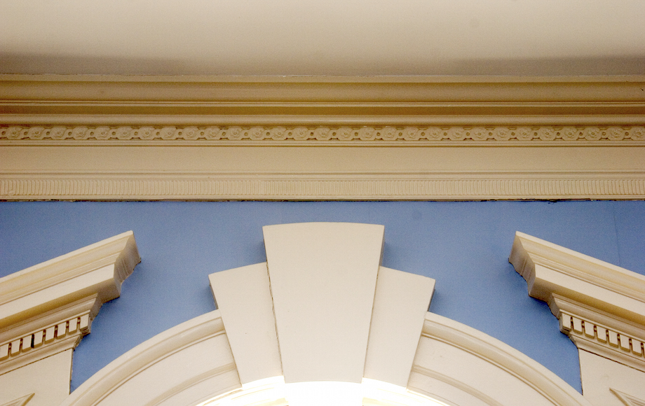
Classical Pediments
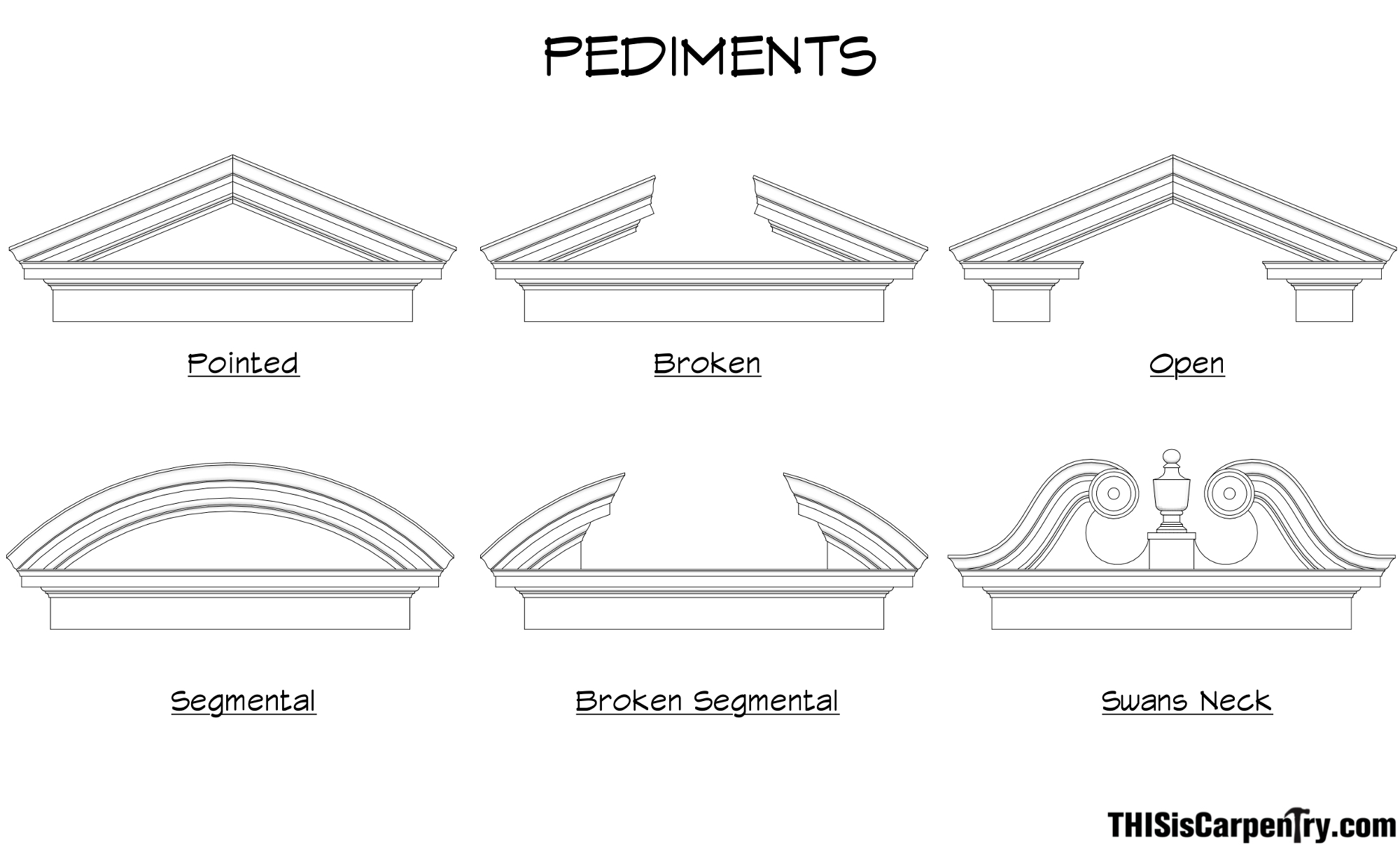
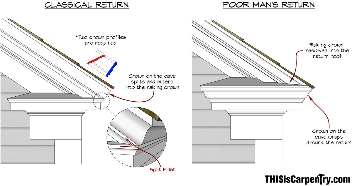
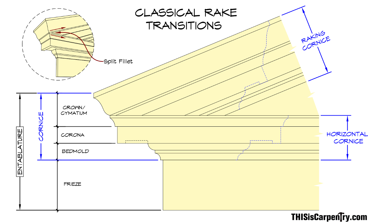
Classical pediments come in a variety of forms. One thing that does remain constant, though, is that their eaves follow the specific order of a classical entablature. As the moldings break around the corner, the cornice splits at the crown molding’s fillet to create a separate raking cornice and horizontal cornice. While the proportions of the parts may differ based on the specific order being used, the crown molding on the eave always remains in its designed position so that its fillets remain plumb.
Moldings are designed to be placed in a specific position so that they reflect light and cast shadows in a particular way. Some crafty carpenters have found a solution to rake transitions by using a single profile. However, in order to make the required rake transition with only one stock crown molding profile, the crown on the eave must be “rolled” or tipped out of position so that it mates with the crown on the rake like a normal outside corner. If the rake is steep, the eave crown can become almost horizontal.
In order to replicate this classical detail correctly, an additional custom profile is needed for the raking cornice.
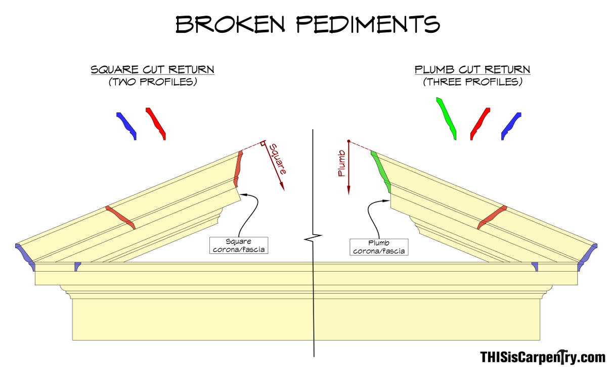
Another difference between classical broken pediments—and one that is much harder to distinguish—is the design of the top return. In many broken pediments—I could cite both contemporary and historic examples—the top return is cut square, which simplifies the required molding profiles. But there are also examples of top returns that are cut plumb: the crown, the corona, and even the bed molding are returned with a plumb cut, which requires an additional molding profile, one that is far more elaborate and almost flamboyantly ornate.
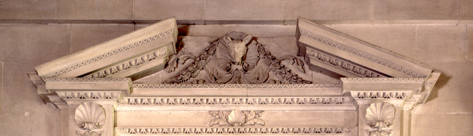
An early Georgian example, the Stone Hall mantelpiece in Houghton Hall, designed by William Kent in the early 18th century, and inspired by Inigo Jones, features a broken pediment with all returns cut square. (photo by G.Katz)
| The main parlor mantelpiece in Drayton Hall was patterned from William Kent’s “The Designs of Inigo Jones,” published in 1727. Several changes were made, but ironically, this broken pediment includes a plumb cut on the returns. (photo by G.Katz) | 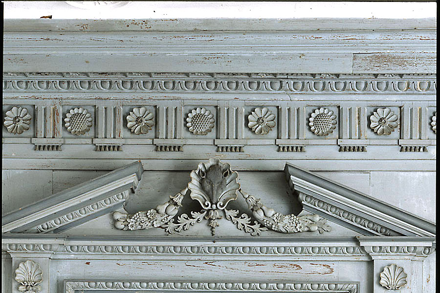 |
Another example of square cut returns can be seen in the Humphrey Sommers home, in Carleston, SC. (photo by G.Katz)
 |
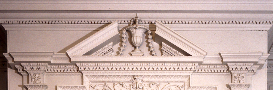
Plumb cut returns are more complicated and therefore more rare. This broken pediment decorates a Palladian window in the stairwell of the Nightingale–Brown House, in Providence, RI. (photo by G.Katz) |
Unbreakable Rules
Nowhere could I find documentation that supported the exclusive use or ‘correctness’ of plumb-cut upper returns over square-cut upper returns. In fact, the choice seems to be one of style: on many simple homes, especially those built for and by tradesman in the late 18th century, square-cut returns were common and more fitting. Whereas, on homes built in the high-Georgian style, plumb-cut returns were occasionally used.
Keep in mind, the return is a small detail—literally, the pieces are extremely short and barely visible. However, the eave return is not a minor detail, and the pieces are easily distinguished and must follow the rules of classical design.
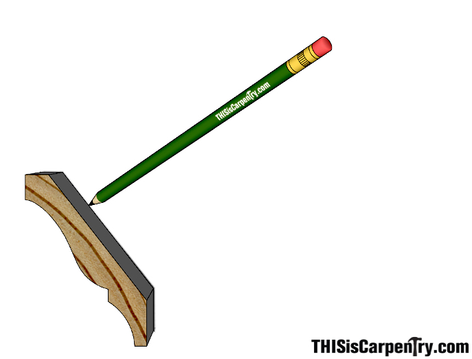
Drafting StepsStep 1: Trace the eave crown molding’s profile in its designed position using a small off-cut of the molding to be used. |
 |
| Step 2: Draw a horizontal line above the traced profile to act as a storyboard of the molding’s projection. | 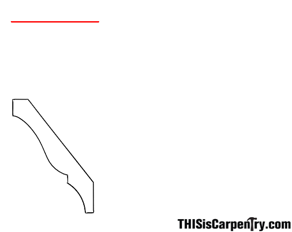 |
| Step 3: Mark off the storyboard by transferring points along the molding’s profile with vertical lines until they reach the storyboard line. Start with important transition points along the profile and then fill in the curving portions with more vertical lines. The more lines you add, the more accurate your new profile will be. | 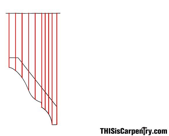 |
| Step 4: Once all of the storyboard reference lines are set along the eave crown’s profile, project guidelines from all of the intersections at the desired pitch angle. Then, add another line above these rake guides to act as a storyboard for the rake profile. | 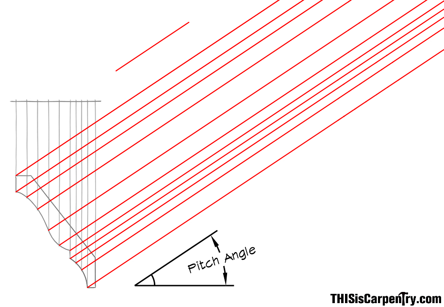 |
| Step 5: Record the information from the eave profile’s storyboard by marking the points onto a storyboard template. Then, reposition the template to the rake profile storyboard line and transfer the points. | 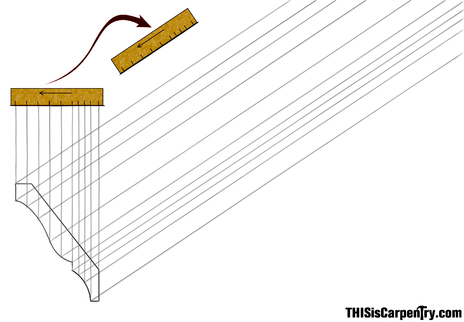 |
| Step 6: Extend perpendicular lines from each point on the rake storyboard line until they intersect with their corresponding rake guide. | 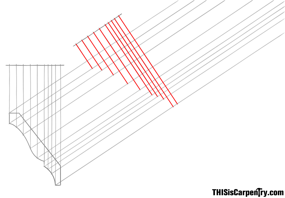 |
| Step 7: Use a straight edge and a flexible curve to connect all the new intersection points and plot out the shape of the required rake profile. | 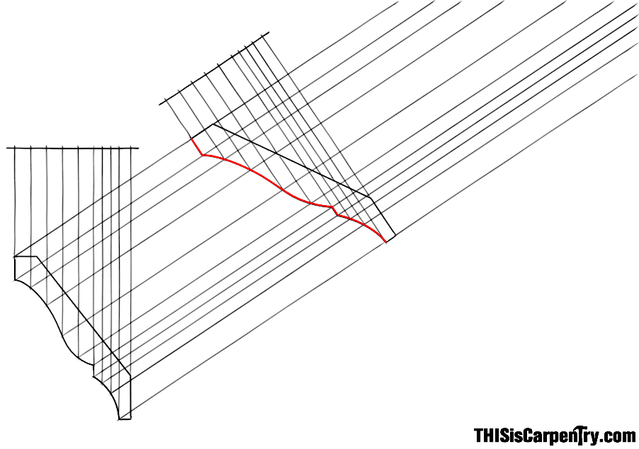 |
This new custom rake profile is the only molding needed for most jobs. However, for more ornate broken pediments—those with a plumb-cut corona, a second custom profile must be developed for the upper return at the top.
| Step 8: Draw a horizontal line above the rake guides for the return profiles storyboard. | 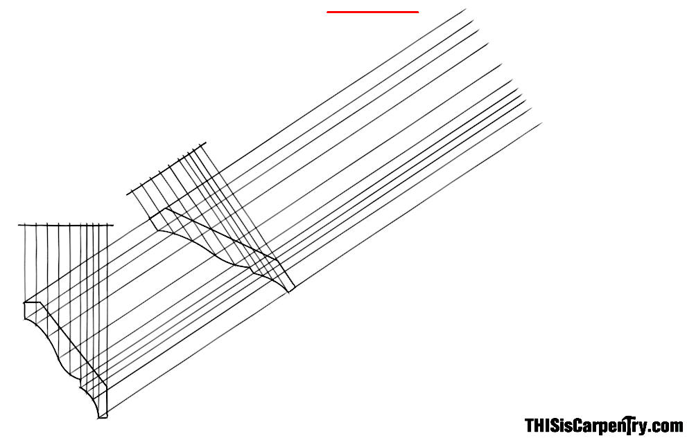 |
| Step 9: Reposition the storyboard template to the rake storyboard line with its projection in the opposite direction and transfer the points. | 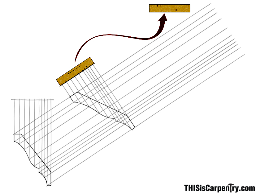 |
| Step 10: Extend vertical lines from each point on the return storyboard line until they intersect with their corresponding rake guides. | 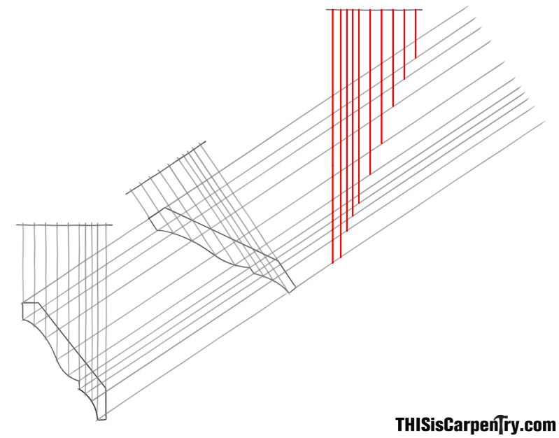 |
| Step 11: Use a straight edge and a flexible curve to connect all the new intersection points and plot out the shape of the required return profile. | 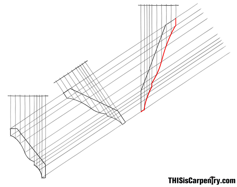 |
A Computer Modeling Alternative
If you’re an avid TiC reader, you already know that we are huge fans of SketchUp. It’s a terrific program for working out designs in 3D and a tool that every carpenter should include in his/her tool belt—especially since SketchUp Make is available for FREE!
Creating 3D models of your projects can not only help you refine a design and work out construction details in advance, it can also help solve geometric problems that were once done only on the drafting board with complex drawings.
Creating an Accurate Profile in SketchUp
Having accurate molding profiles in your drawing is useful for creating a realistic representation of the final product. For basic renderings and shop drawings, their exact size and shape isn’t that important. But, if you plan to use a specific profile to develop another profile, accuracy is VERY important (garbage in-garbage out).
You can find a lot of CAD files online for molding profiles that are helpful, especially if you are using SketchUp Pro. Some progressive molding manufacturers, like WindsorONE, are also now including their profiles in the SketchUp 3D warehouse. While these downloadable files are great resources to have, you can’t always count on having the profile you need available, or that the profile you download is accurate enough. Sometimes you might need to re-create a custom profile for a specific job, too.
In the following videos, I’ll go through my method for creating an accurate copy of a given molding profile in SketchUp, and then share some advanced techniques that can be used to develop the rake and return profiles.
Once the required profiles are developed and the molding is produced, you’ll still need to know how to cut them to fit. Here are the basic cuts at a glance.
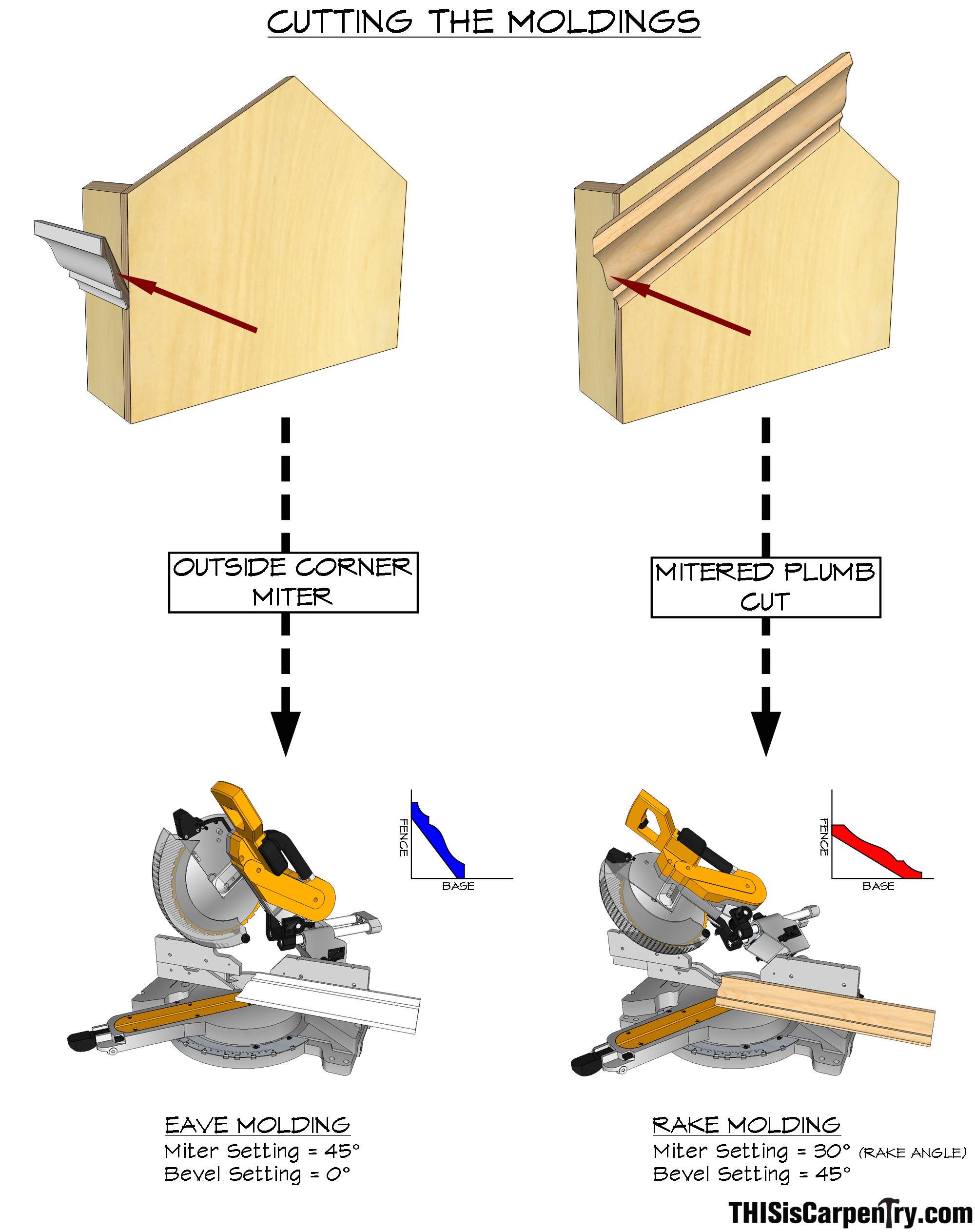
If you’re cutting ‘in position,’ the horizontal crown is cut exactly the same way as any other outside corner—nested upside-down in the saw, the base of the saw represents the ceiling or the top of the crown. Simply swing the miter to 45 degrees, so that the miter cuts through the edge of the crown.
The rake crown is a little more confusing because it must be cut right-side-up, so that the miter is cut through the face of the crown. The thing to keep your eye on is what part of your saw represents what. Also, when cutting the rake crown, the miter setting must be swung to the pitch or rake of the roof (in this example that’s 30 degrees), while the bevel is rotated to 45 degrees to create the mating miter with the eave crown.
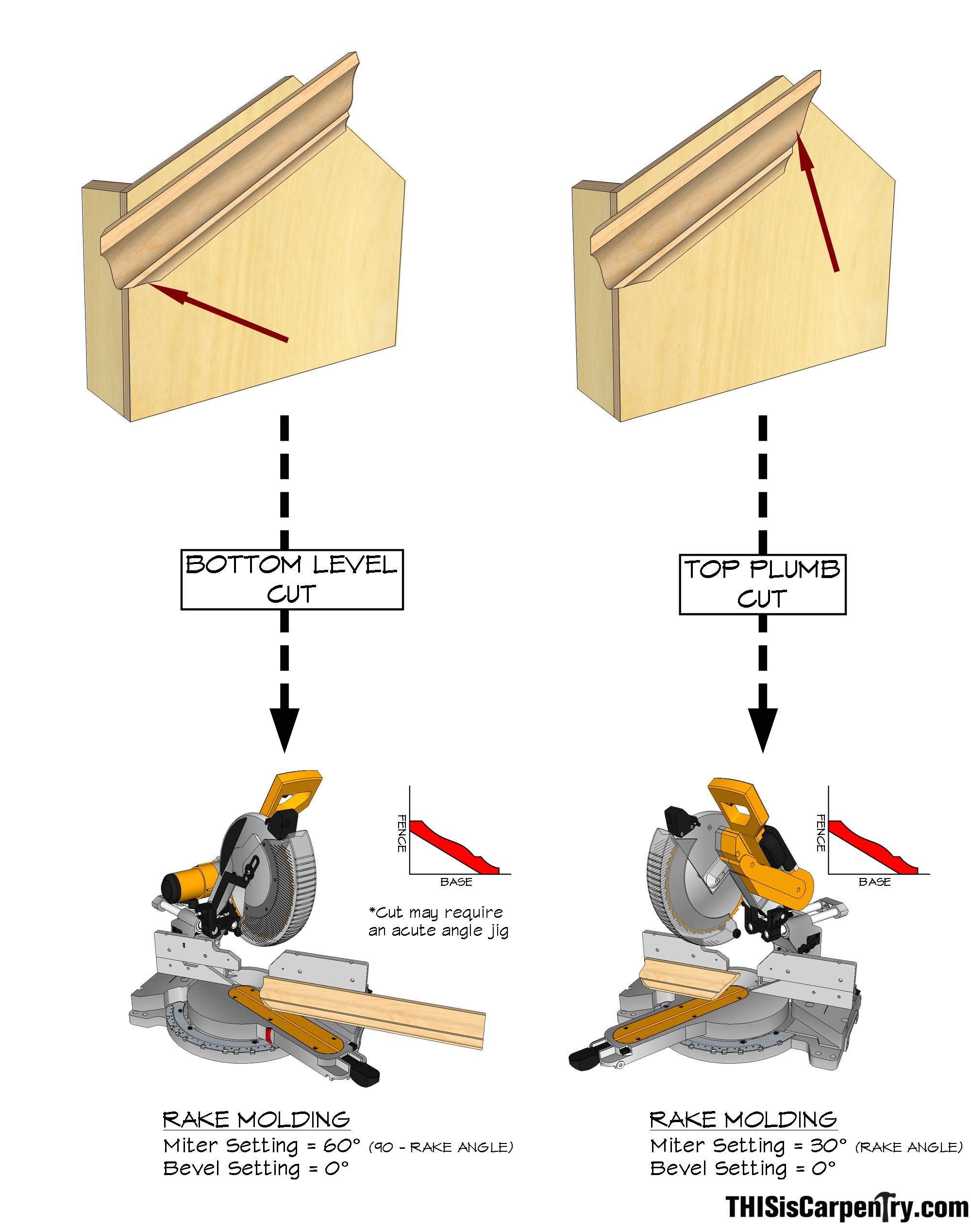
Nipping the fillet off the bottom of the rake crown will probably require an acute angle jig—even if the rake is more than 30 degrees, you can only miter to 60 degrees on the right side of most miter saws (Note: some molding profiles may require that this cut is done carefully with hand tools, so that the cyma portion of the profile is not disturbed). But you won’t need an acute angle jig for the ridge miters—simply position the crown so the fence represents the roof or ceiling, and set the miter to the pitch angle.
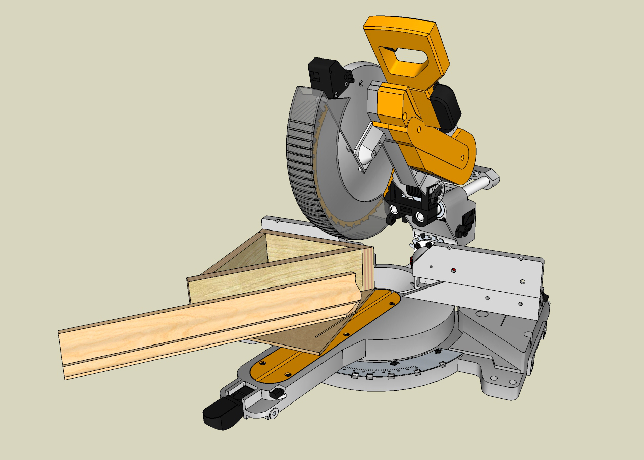
An acute angle jig will expand the capacity of any miter saw, and can make cutting sharp angles much easier and safer.
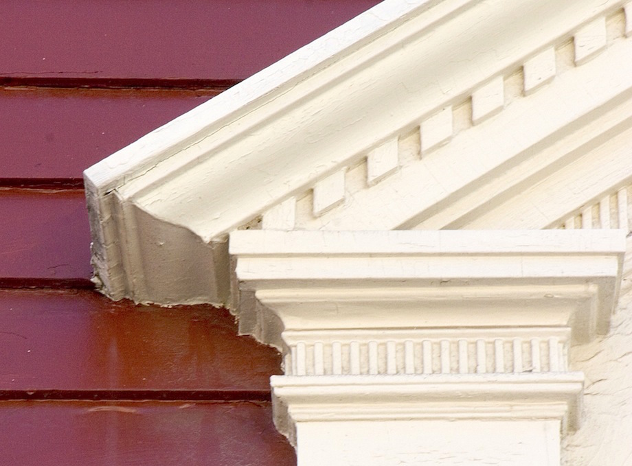
While this level of detail normally isn’t within the scope or budget of most contemporary projects (no doubt the reason for the aptly-named “Poor Man’s Eave Return!”), it’s a classical detail that was once very common. Even if you never go through the process yourself, I hope you will now be able to recognize it when you see it and appreciate the work that is involved. I know I’ve walked right past this detail many times in the past, without ever realizing its complexity.
Folks, one fine article. I’m looking forward to more details, particularly how to (hand?) fabricate the return profiles. Guess I need to finally make a good acute angle jig! Thanks
Wow. What a well written article. Todd, you provided everything just short of actually doing the job. Thank you
Great Sketchup video’s, thanks.
As usual, I learned some new tricks.
Thanks.
Tim
I was so impressed with the drawings that I immediately printed the article
I’ve been waiting for this article for a long time. Thanks! One of those carpentry secrets that was really hard for me to figure out.
Excellent article Todd. Thanks for posting this:
“Reposition the storyboard template to the rake storyboard line with its projection in the opposite direction and transfer the points.
”
That is what I was missing.
Sim
Very well done! Very clear to follow along and love the developed drawings for the crown.
Thank you, well done.
This article makes Ernest Joyce’s explanation of laying out a pediment for a tall boy much easier to understand.
Knowing how to do things the right way is the beginning of being a Craftsman. Not that we always get to do it that way.
Gold!
I am a humble homeowner. But I’m learning! I’m considering attempting a pediment over my front door and would love to try a “correct” eave and raking crown. Split fillet and all.
Can you buy matching eave and raking crown at lumberyards or is it always a custom fabrication? Since my project is from scratch, I can use any rise/run.
This article was amazing. I walk around my historical neighborhood with a better understanding of the effort involved in getting it right.
Thanks!
Matt,
Thanks for the comment and I’m glad you enjoyed the article.
You’re probably not going to be able to find matching level and rake crown at most lumber yards. It’s a very specialized item, and the required rake crown profile will be different for every pitch. There are some specialty restoration millwork companies that do stock certain matched crown profiles and fillet moldings. One of our readers pointed us to http://www.jpmoriarty.com in Boston. The one set I looked at appears to be developed for an 8/12 pitch–but you may be able to modify it for a shallower pitch.
Good luck with your project!
Todd
great article! i have bought my self a wood master molder a few years back to keep my custom moulding in plane around rakes!
great article
really enjoyed the read!
good luck
Luke
Can this same principle be applied to develop rake profiles for installing crown on vaulted ceilings? And if so, can you tell me how would the miter saw set up differ for inside corners where two different profiles come together?
Greg,
Yes, this technique can be used to develop matching rake and level profiles for an interior corner transition. During layout it’s important to keep the direction of the moldings projection in mind. For an inside corner the molding projects in towards the molding on the rake wall. This creates a rake molding that is actually smaller than the one on the level run, as opposed to an outside corner, where the rake molding will be larger than the level profile. If the pitch of the ceiling is steep, the rake profile can become very foreshortened and create an awkward looking profile. While the geometry works for this application, I’ve never seen an historical example of it used in classical architecture (or crown molding used on a vaulted ceiling at all for that matter). Personally, I feel it falls into the category: just because you can doesn’t mean you should… But that’s just me!
As far setting up for the cuts—the setup it the same, except that the 45° miter on the level molding and the 45° bevel on the rake molding are swung in the opposite directions to create a mitered inside corner.
Todd
Here is an illustration of the molding installed…
Perfect sense! 👍🏻👍🏻👍🏻
Very nice article. While it is true this is a small detail, it is one that has become a benchmark of sorts when evaluating the quality of work either architecturally or in furniture. The effort involved makes it a good visual clue as to the thought and care given to the rest of the project.
This detail as well as the correct placement of classical columns in relation to the beam, are very indicative of quality, thought and good design. The latter is perhaps the most abused since columns are ubiquitous in all work, but seldom placed correctly.
This is well presented and very usable for anyone truly interested. I have seen the same concept used for items like chair rails that need to be not as thick, for various reasons, on one side of a miter.
Hi,
Is an inside corner cut the same way or is there a transitional piece necessary? I have a 90 degree horizontal inside corner and then a 30 degree pitch up.
Bob
A transition piece is only needed if you are using the same molding profile on both the level and rake runs, and, maintaining the designed spring angle on both pieces of crown. See comment #12.
It was interesting to know that the rake crown must be cut right-side-up. My friend told me that their project involves flexible crown molding. I think it’s best to partner with a contractor with the right tools for the job.
This is lowkey better explaination of pediments than most of the architecture sites/articles. Good job.