


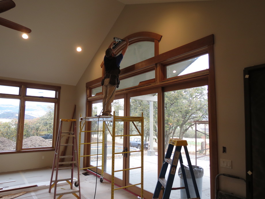
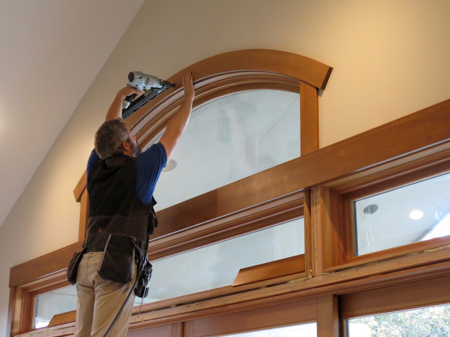
Lately, my crew and I are installing a lot of flat stock casing in the homes that we trim out—which means I also have to make more and more radius casing to finish the tops of windows and doors that have arched heads. Besides the sizes of the openings always being different, some openings require a full semi-circular arch, while others require just a segmental arch. And occasionally we make radius casing that’s stained and top coated with fine finish. That’s when it’s even more important to get a perfect fit and a good grain match, too!
(Note: Click any image to enlarge)
Like a lot of finish carpenters, I’ve struggled to figure out a full-proof system for cutting radius trim on the jobsite. With the help of Gary Katz—and especially Todd Murdock, I’ve developed a dependable approach and have battle-tested it to be sure it’s accurate. Here’s what works best for me and my crew.
Measure the opening
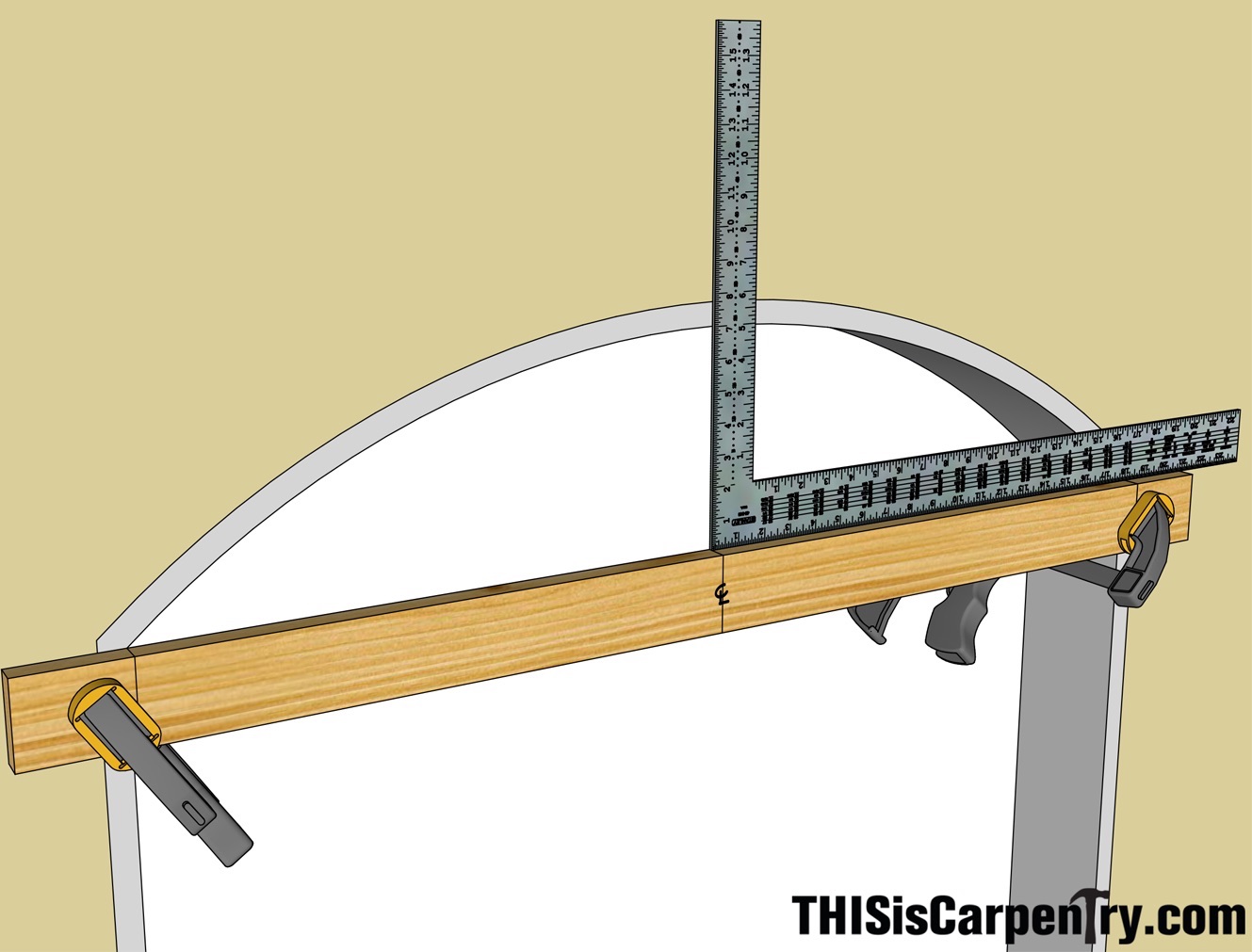
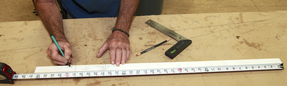
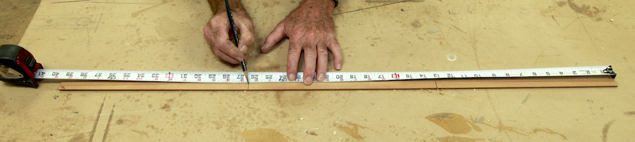
The first step is simply to see what you’re working with. Measure the opening carefully. Measuring the width is easy; just make sure you do it right where the leg jambs intersect the head jamb. This measurement is called the “chord length.” To measure the rise, I screw or clamp a straight edge horizontally at the intersection of the jamb legs and the head jamb. Then I mark the center of the jambs on my straight edge and measure up, at that location, to the inside dimension (ID) of the head jamb.
The ID of the jamb is what all of the casework must be registered from. If you want, you can also mark the ID of the jamb legs right on your straight edge so that you can easily transfer the chord length onto your work table.
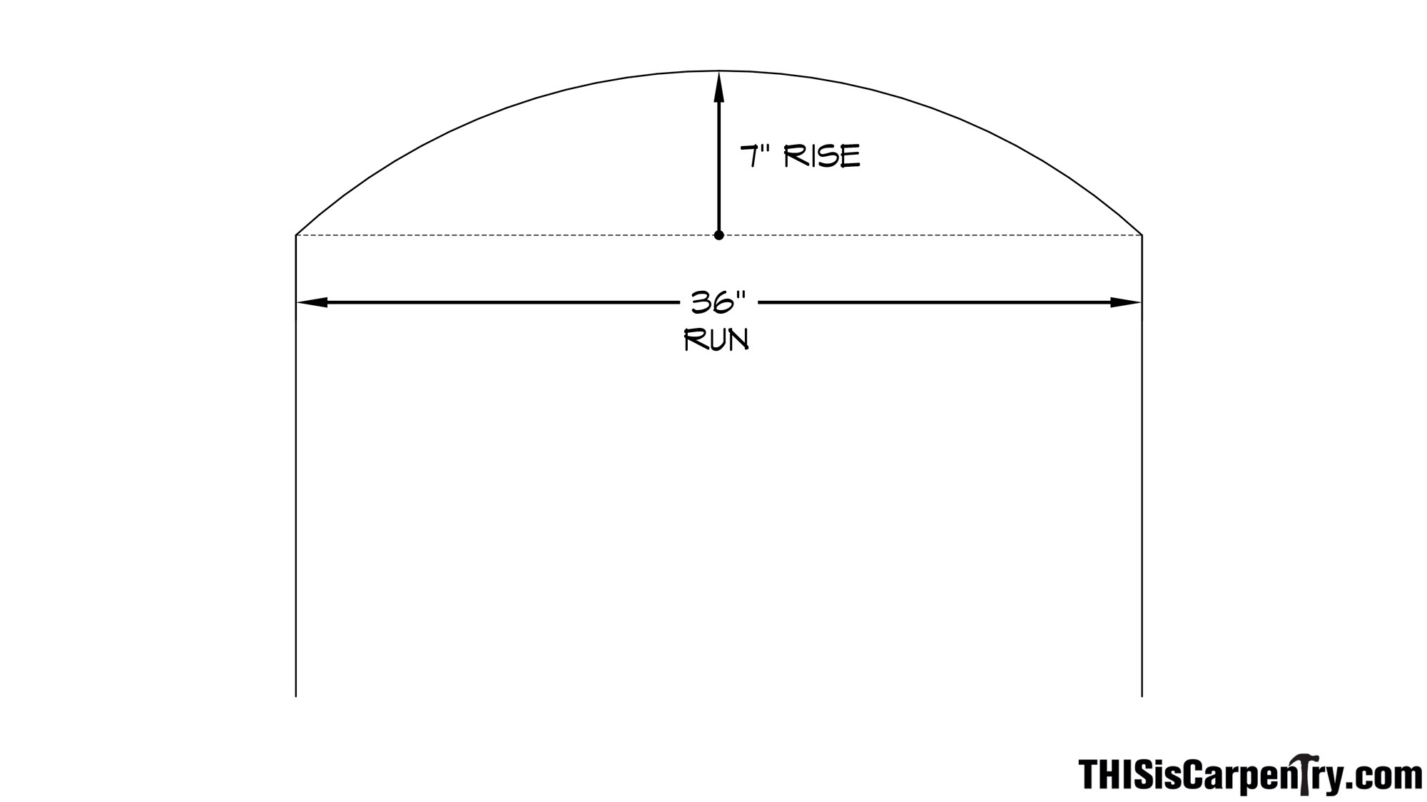
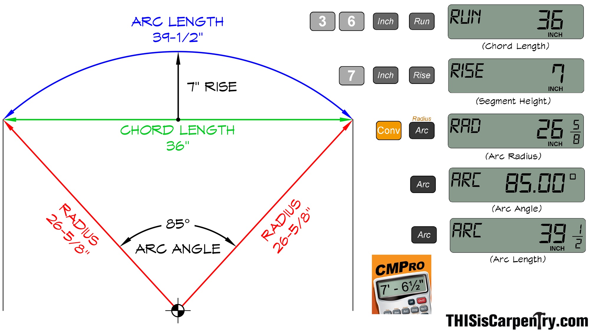
The arched opening I’ll be using as an example in this article measures 36-in. wide at the ID of the jambs and has a rise of 7 in.
Believe it or not, with just these two simple measurements and a construction calculator, I can easily determine everything else I need to know to create the radius head casing. But before I get into the calculations, I want to review the terminology used for describing parts of a circle so that we’re all visualizing the same thing.
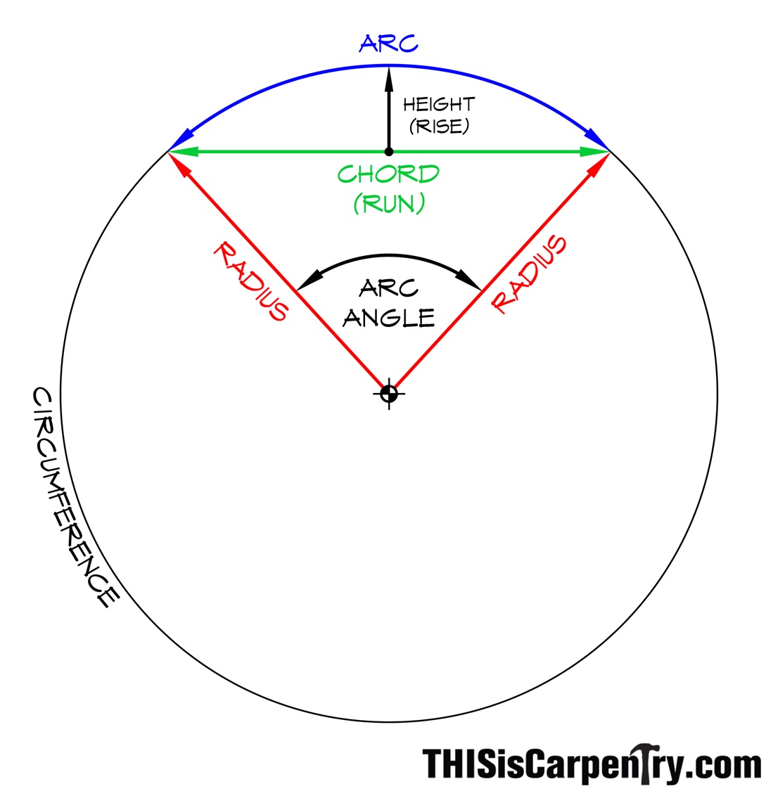
Arc: A portion of the circumference of a circle or other curve.
Arc Angle (arc measure): The angle formed by the arc endpoints and the center of the circle.
Arc Length: The distance along the curved line making up the arc.
Chord: A line segment joining two points on a circle or curve.
Circumference: The distance around the perimeter of a circle.
Radius: The distance from the center point of a circle to its perimeter; equal to one half of the diameter.
Using my Construction Master Pro calculator, I start by entering the chord length; punching 36 in. into the calculator and then pressing the RUN key (don’t forget to press the INCH key after you enter a measurement!). Next I enter 7 in. and press the RISE key. To solve for the Radius, you must first press the CONV key to access the calculator’s secondary key function, and then press the ARC key (note the Radius label above the Arc key). The radius in this example is 26 5/8 in. Next, press the ARC key again to find the Arc Angle—85° in this case. Pressing the ARC key a third time will even give me the Arc Length—39 1/2 in. While the Arc Length isn’t something I specifically need to know for this job, it’s useful information that can be valuable for other types of radius work.
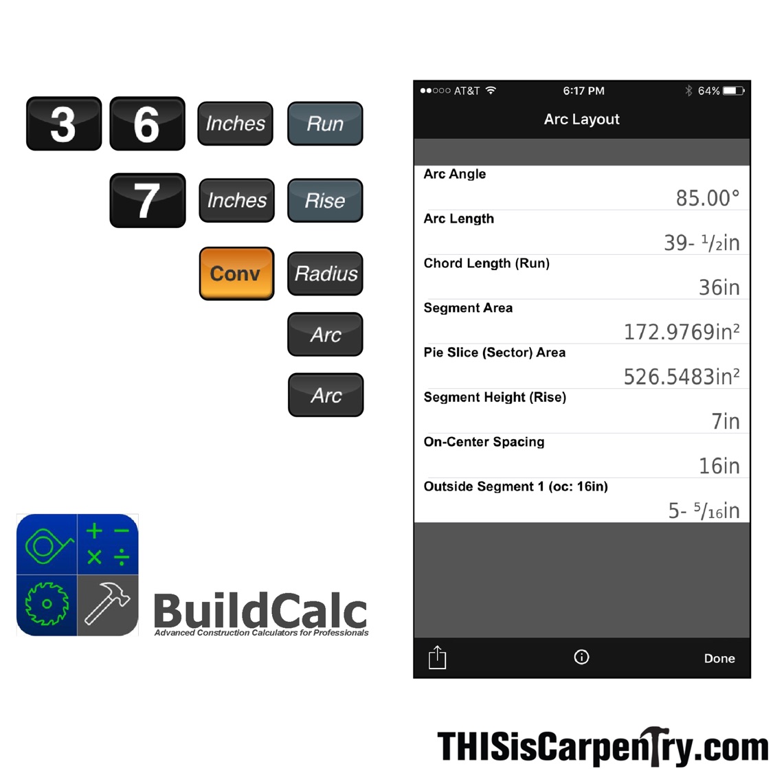
If you’re using BuildCalc, all of the keystrokes are the same, but you’ll notice that after you press the CONV key, the label on the Arc key will automatically switch to “Radius.” AND…when you press the Arc button the second time, the screen will switch to an enhanced ‘Arc Layout’ page. It’s like a virtual note pad. You can even email or print the results right from the App!
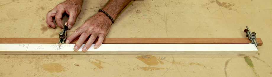
Don’t wait to start jotting down the results from your calculations—I always do that right near my worktable. Trust me, you can’t remember all the figures and you’ll need to reference them over and over again. A written list helps me stay organized and avoid silly memory mistakes.
Make a story pole
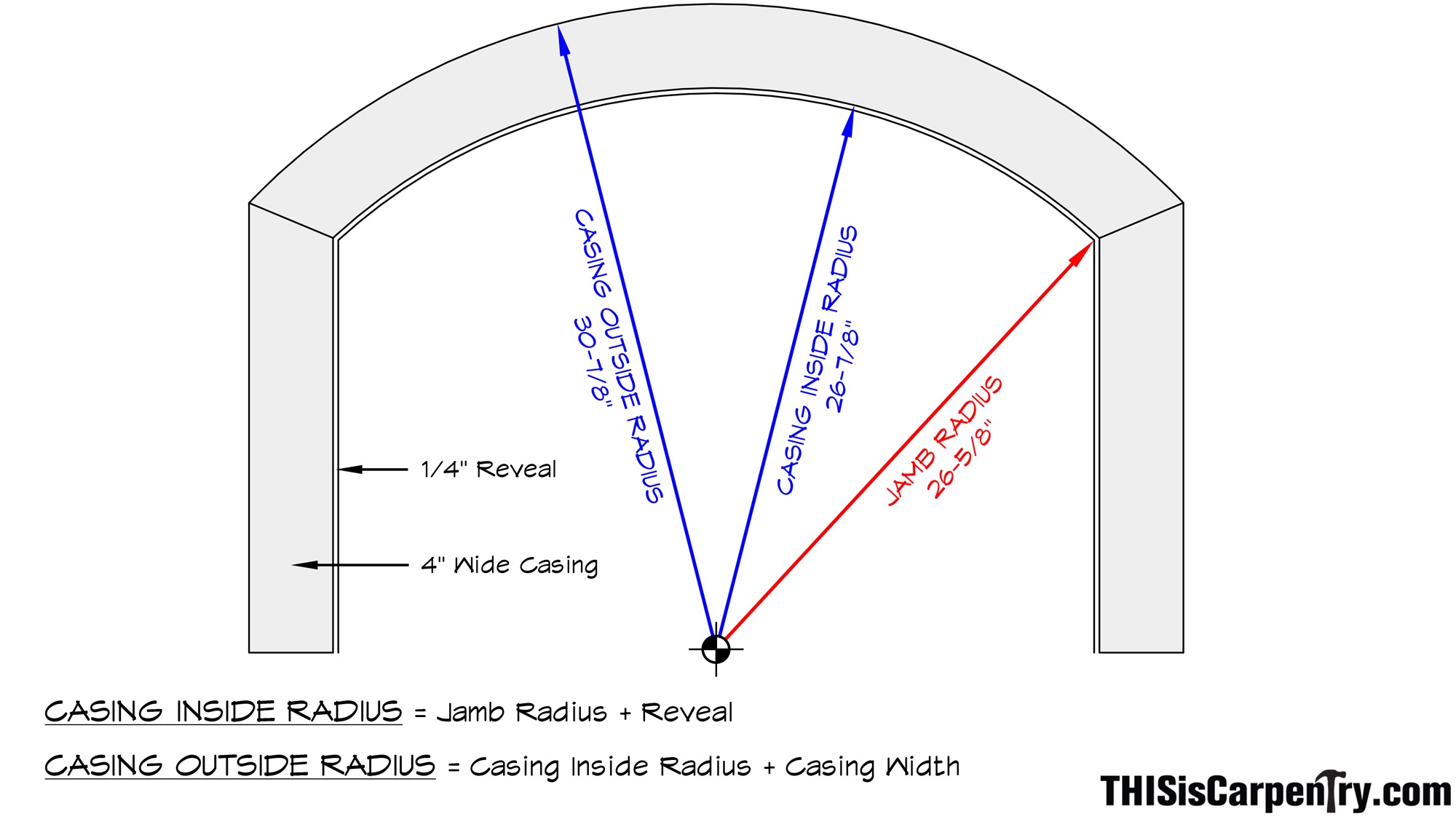
With the head jamb radius established, I can now determine the inside radius and outside radius of the head casing. In this example I’ll be using 4-in. wide flat casing with a 1/4-in. reveal. Knowing the reveal dimension is important! If you’ve ever had to fight hard to get even reveals while installing radius trim, there’s a good chance the reveal you were trying to achieve was never accounted for when the trim was milled.
For this type of layout I’ve learned it’s best to make a story pole. Gary Katz is getting older and repeats himself a lot. One thing he never stops talking about is the stuff he’s learned from other carpenters, especially Jed Dixon, the stair builder who taught him to always make a story pole. Now I do the same thing whenever I have to lay out anything with more than two dimensions!
I start with a piece of scrap and make a clean square-cut on one end. Then I hook that end with my tape and make a mark for the jamb radius. Next I add a 1/4 in. for the reveal between the inside of the jamb and the IR (Inside Radius) of the casing, then I make another mark 4 in. further to define the OR (Outside Radius) of the casing.
This story pole is absolutely essential and critical to maintaining precision and repeatability—something that cannot be achieved by pulling out a tape measure every time a measurement must be set. As you’ll see in this article, I return to the story pole repeatedly to set dimensions.
Make a pencil trammel
If you’ve ever used trammel points to help layout and draw your work, then you know how precise they can be—as long as you keep your pencil very sharp, and as long as you adjust the points precisely!
| That is why I always use the story pole to set my trammel points. I attach my trammels to a sanded piece of 1/2-in. x 1 1/4-in. stock that’s just a few inches longer than the Outside Radius of the casing. |  |
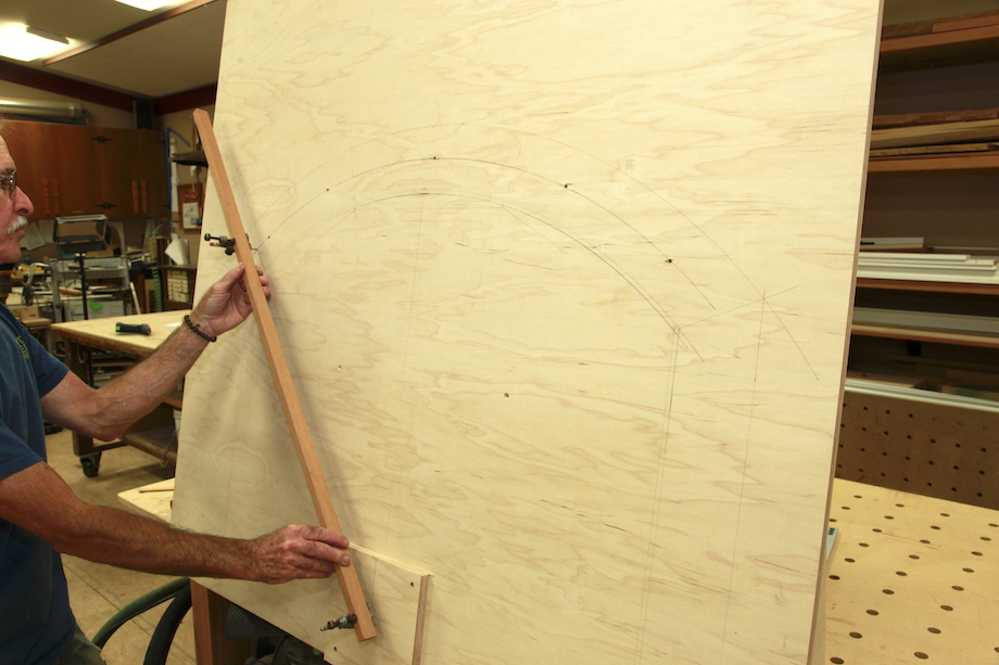
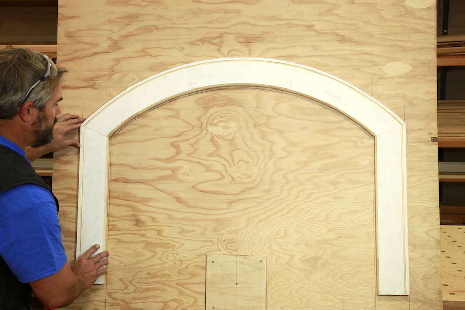
Make a full-size drawing
I start with a full-size drawing on a large piece of plywood—big enough to use as a worktable and router table. First, I strike a center line, and install a spacer block. The spacer block needs to be the same thickness as your casing material to elevate the router trammel arm and maintain a level plane. We’ll get to that soon.
| Next, I mark lines that represent the inside edges of the jamb legs, being careful to lay them out equally from the centerline. Then I drill an 1/8-in. hole on the center line, right into the spacer block, establishing the center point for all of my radii. | 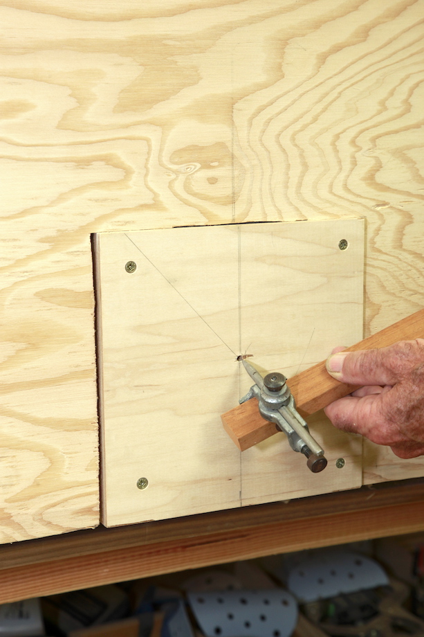 |
That’s when I turn to my story pole the first time.
By simply registering the steel pivot point at the end of the story pole, and setting the pencil point at the jamb radius mark, I can maintain a much higher degree of accuracy than trying to set the trammel points to a tape measure that can’t be held still. I use the same technique for setting the trammel points for the IR and OR of the casing, too, and that’s not all…
| Don’t forget to sharpen the pencil until it’s a needle! That’s the only way to maintain consistent accuracy. | 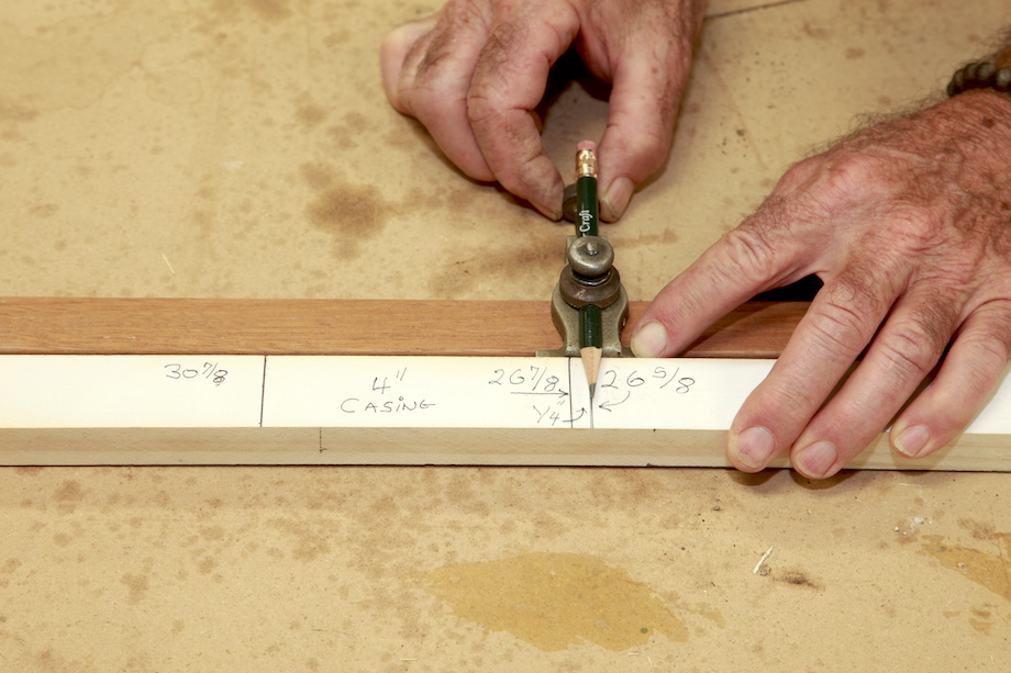 |
|
Trammels are fantastic tools. They’re easy to setup, easy to swing, and you can still find antique iron trammels on eBay! I place the steel point into the pivot point on the centerline… |
| …then I swing the pencil for each arc, starting with the IR of the jamb, then the IR of the casing. Each time I adjust the pencil trammel to a new radius, I use the story pole to be sure it’s dead on. | 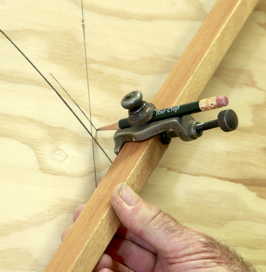 |
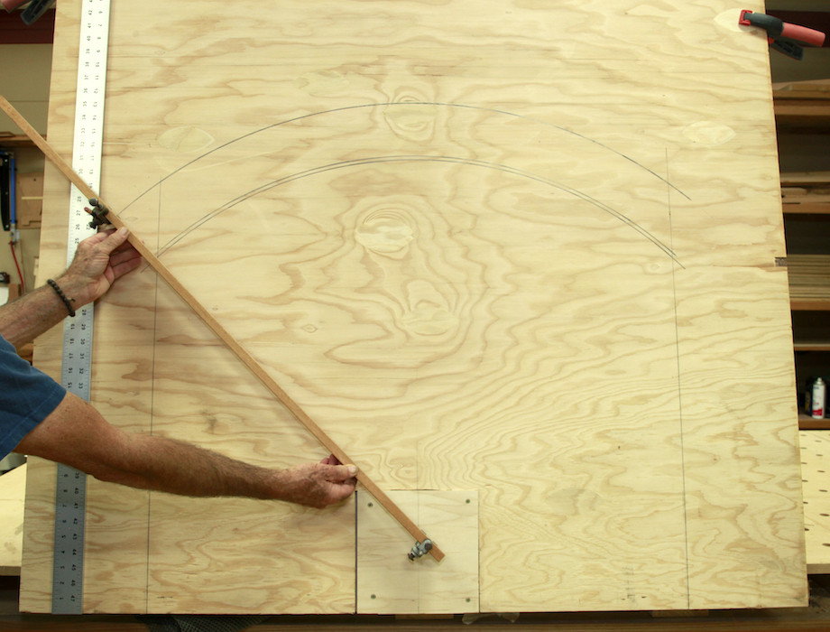 |
The last arc is the OR of the casing. |
Anyone with a sharp eye probably noticed that I have a sheet of 1/4-in. plywood clamped on top of the backboard. This is a set I use at JLC LIVE!, so we can draw those arcs over and over on a clean sheet. Otherwise the backboard, with all the router grooves cut in it, becomes really distracting.
Make a router trammel
Once again, the story pole helps me layout one last critical component for this radius casing project—a router trammel arm. Yes, you need to make two trammel arms—one for your sliding trammel points, and one for your router.
I use a piece of 1×6 that’s around 12 inches longer than my story pole and strike a centerline down the middle lengthwise.
Next, leaving enough room from the end of the board to comfortably mount the base of the router, I’ll strike a perpendicular line plotting the center of the router cutter.
I like to use a 1/2-in. upcut spiral router bit to cut the actual casing. I prefer the half inch cutter because it fits so nicely into a 5/8-in. template guide, which I find to be a little more interchangeable between my different routers—that’s the template guide I use on all my hinge and lock templates, too. But you could use any size bit and any size template guide.
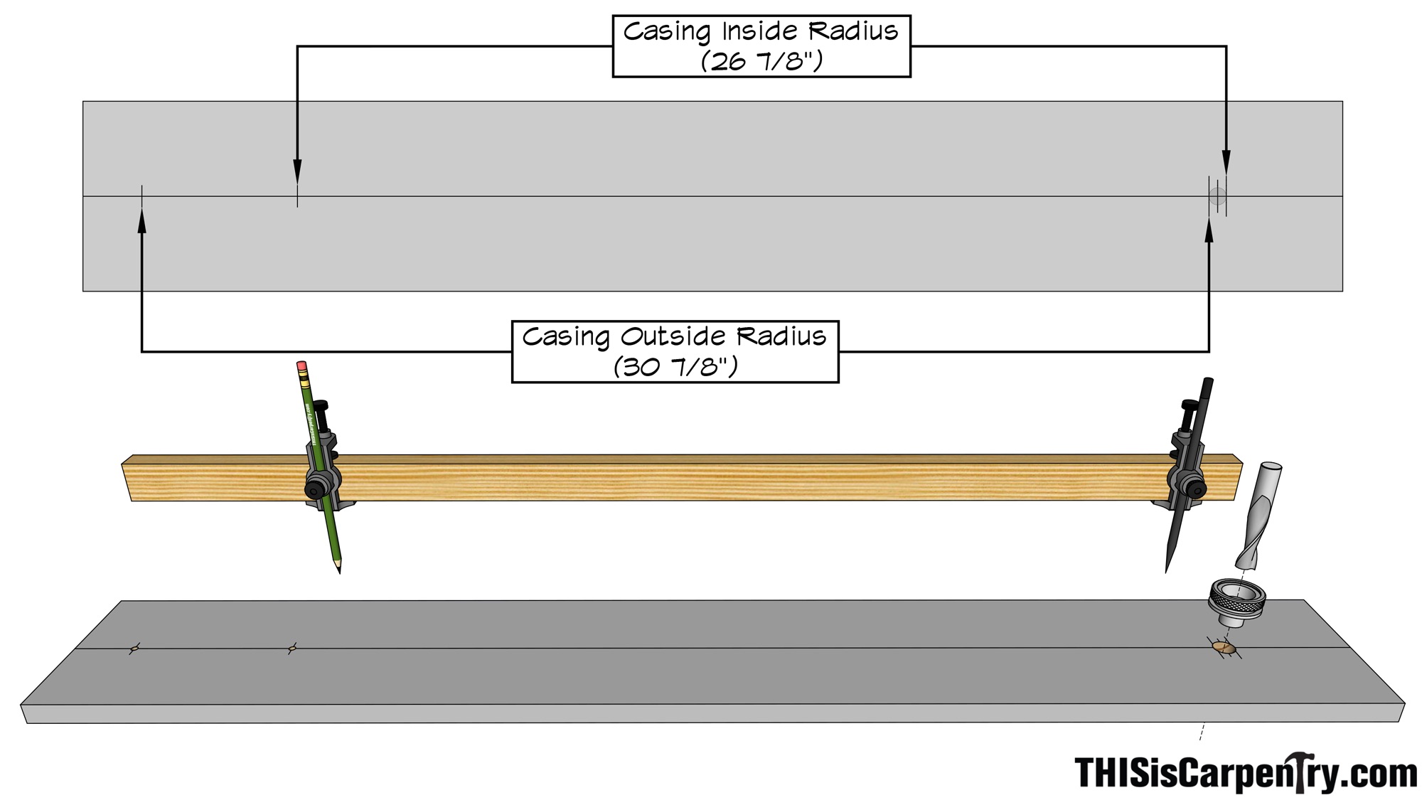
Just remember this: The OUTSIDE of the cutter will be cutting the IR of the casing; and the INSIDE of the cutter will be cutting the OR of the casing. To establish the INSIDE and OUTSIDE of my cutter on the story pole, because I use a 1/2-in. router bit, I measure and mark 1/4 in. on each side of the center-of-cutter line.
| To maintain as much precision as possible, I use a sharp nail set to strike a pilot hole at the center of the cutter, which helps guide my 5/8-in. drill bit. | 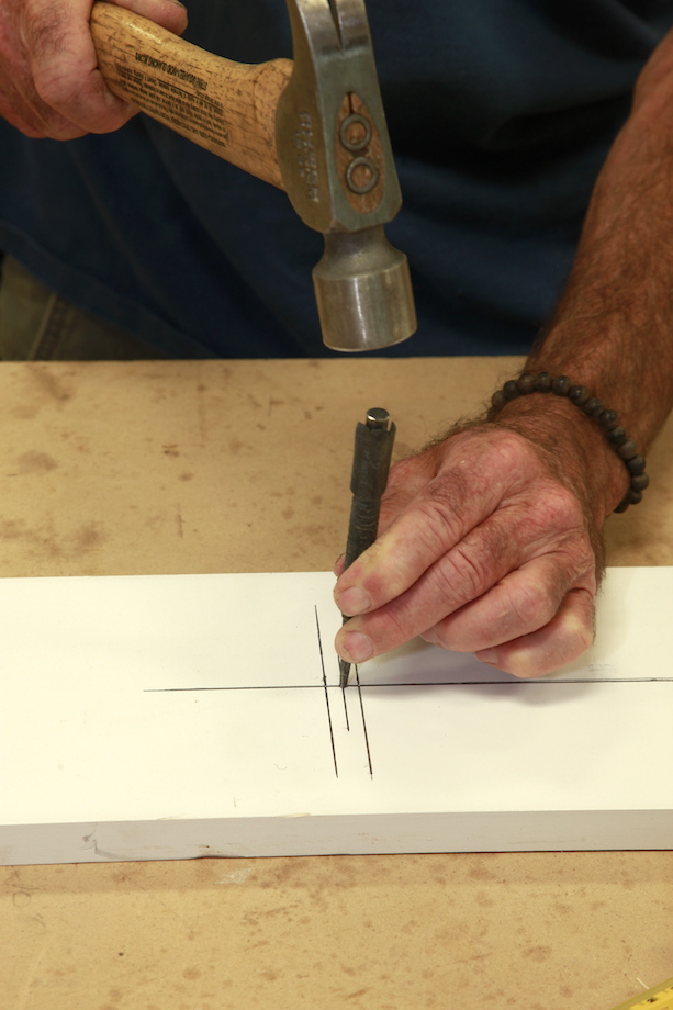 |
Now it’s back to the story pole! Holding the butt end of the story pole even with the outer line (the OUTSIDE of the cutter)…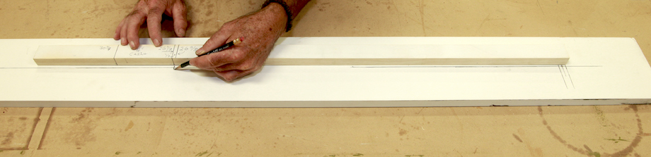
| …I transfer the IR of the casing on the story pole to the router trammel. | 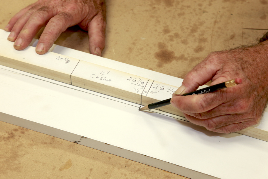 |
| Next, holding the butt end of the story pole even with inner line (the INSIDE of the cutter)… | 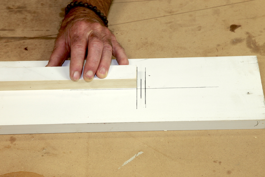 |
| …I transfer the OR casing mark to the router trammel. | 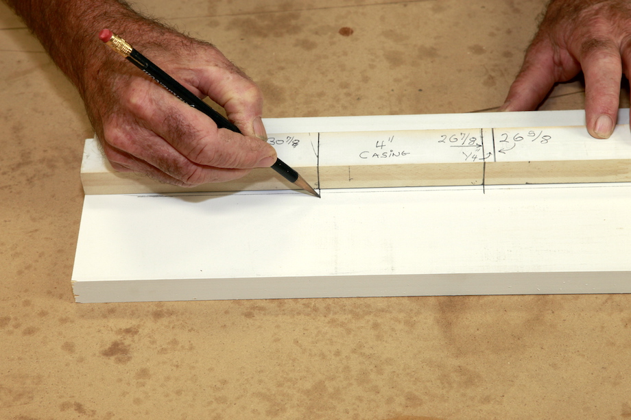 |
Finally, using that same sharp nail set (or an awl if you’ve got one!), mark and drill the intersections precisely.
| Because I use a 5/8-in. template guide, I drill a 5/8-in. hole at the center of the cutter for the template guide—I want a snug fit. | 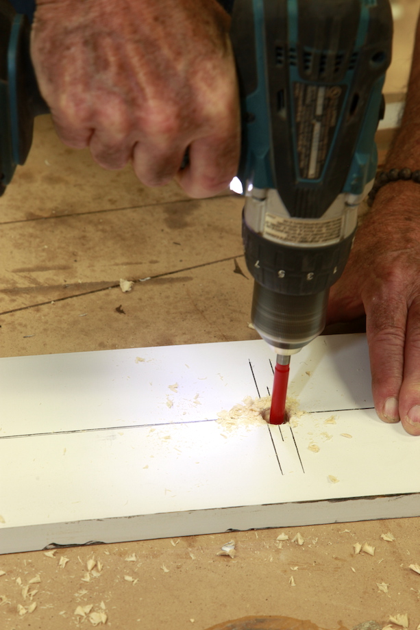 |
| And because I use a #10 washer-head screw to secure the trammel arm to the center block, I drill a 3/16-in. hole at each of the two other intersections (the pivot points for the IR and OR of the casing). | 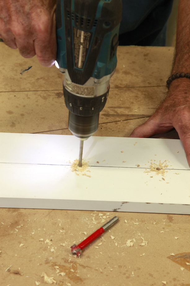 |
How many pieces make up the blank?
For me, the number of pieces required to make up the blank is determined by the width of stock I have on hand, and the size of the radius; for stain-grade jobs, I like to maintain as much grain continuity as possible—I want to avoid the appearance of any horizontal or level grain, which ruins the look of the radius trim!
Picking the number of pieces requires a bit of common carpenter-sense, but not a lot of mental gymnastics. I just hold a few pieces of stock over my full-size drawing until I’ve determined the proper number of pieces. If you have enough time to plan ahead, do a quick Sketchup drawing of the opening—that’s a sure-fire way to determine everything you need to know about the layout, and that’s the method I used for this article. I chose to use three pieces or segments to make up the radius casing.
Determining the lengths and miter angles
There are several ways to determine the lengths of each segment, and the precise miter angles for the segments, too. And no, you don’t have to cut a bunch of small pieces and experiment until you get the right angles! When it comes to this task, construction calculators really earn their keep.
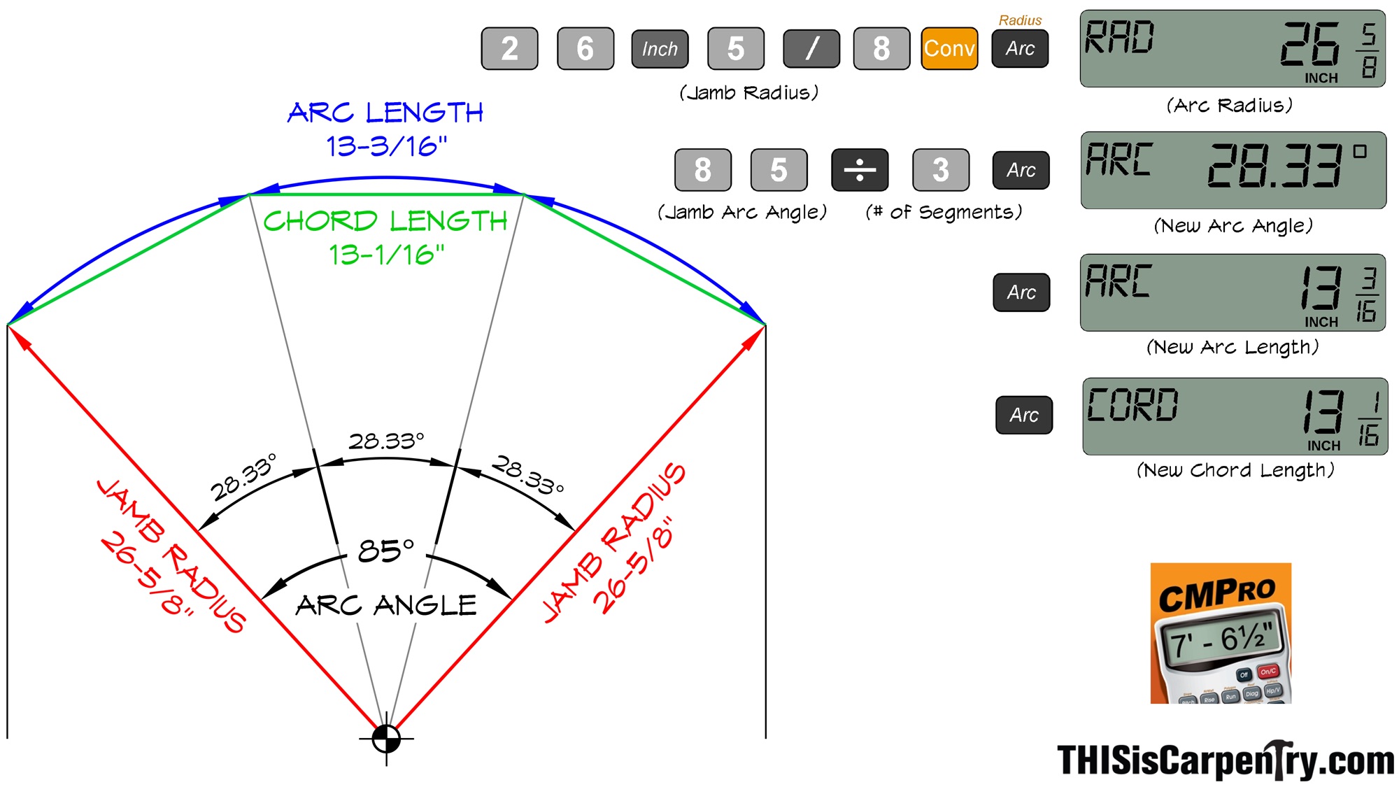
Since I’ve decided to use three pieces to construct the blank for my casing, I simply need to divide the arc angle of the head jamb into three equal segments. By entering the jamb radius and the new arc angle into the calculator I can work backwards to find the new chord length!
Start by entering 26 5/8 in. (Jamb Radius) into the calculator followed by the CONV key and then the ARC key. Next, enter 85 (Jamb Arc Angle) divide it by 3 (number of desired segments) and then press the ARC key to store the result as the new arc angle. Now press the ARC button again. The result is the new arc length—not something we really need. What we’re after is the freakin’ short point-to-short point measurement, from miter to miter. To get that measurement, just press the ARC button one last time. That’s the new CHORD length!
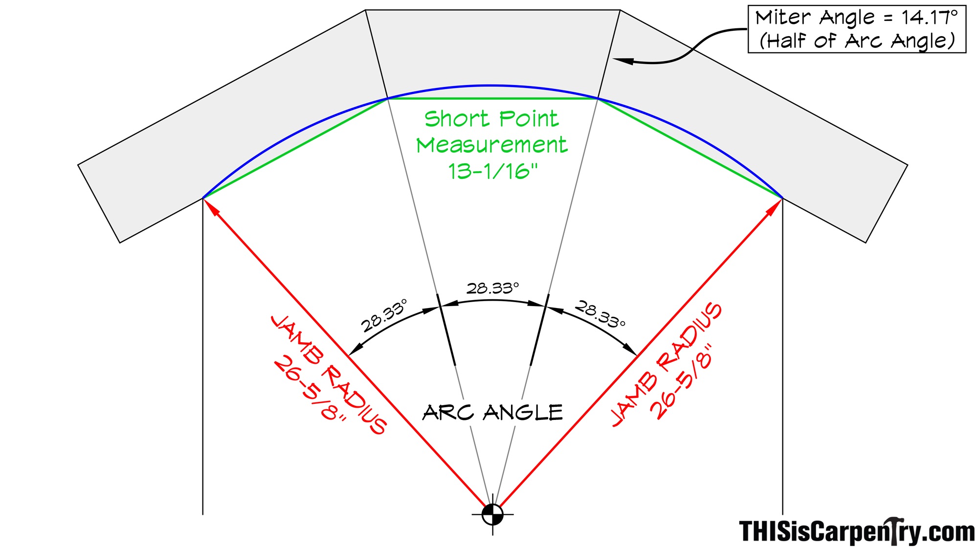
Of course, you’ll want to know the angle of the miters, too. That’s simple: just divide the new arc angle (28.33) by 2. The miter angle is 14.17˚. Yes, construction calculators are awesome, but I’d probably set my miter saw at 14˚ and call it good.
The Egyptian Method
Of course, there’s another way to do this. If you’re an old guy and you can’t keep up with technology or you’re intimidated by trigonometry on a calculator (I won’t mention any names!), you can always do what Gary Katz does—use the Egyptian Method. We call this the Egyption Method because it’s time tested, pretty simple, and incredibly outdated (it’s also not nearly as precise!).
Start by ripping a flexible piece of wood or PVC—if it’s wood make it about 3/16-in. thick, so it won’t snap, and use mahogany or something strong and pliable. That’s why a thin piece of PVC works well, too. Cut the piece to the length of the overall Arc Length, in this case it would be 39 1/2 in. Next, divide the Arc Length by the number of pieces that are required to make up the blank (39 1/2 in. / 3 = 13 3/16 in.).
Measuring from a butt end, mark the Arc Length for each segment.
Next, hold that ‘story stick’ on the radius and mark those tick points.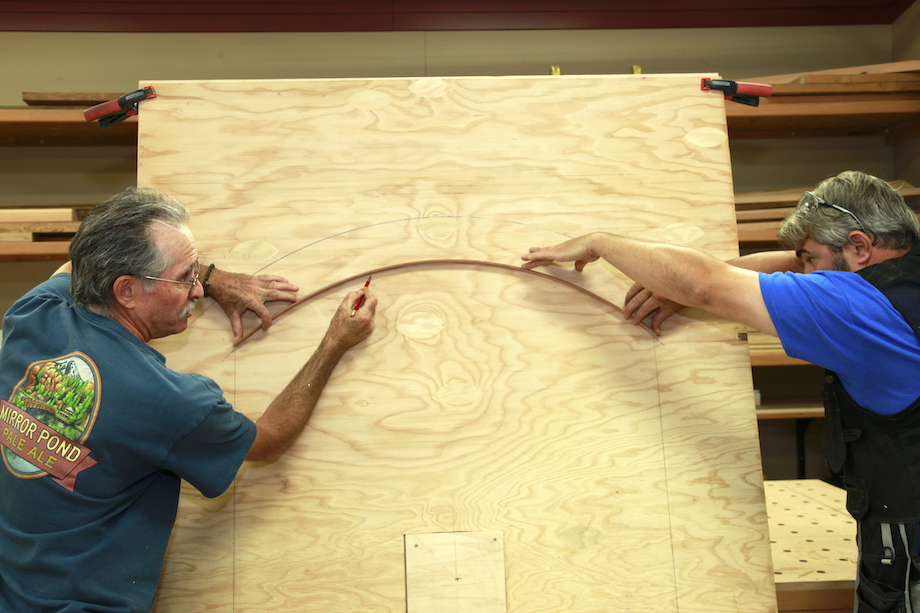
Then measure the cord length from tick point to tick point. Yeah, it takes two guys just to hold that story stick on the radius line! And it’s nowhere near as accurate. But sometimes you just have to exercise patience and let the old guys have their way!
Cut and assemble the pieces into one blank
Cutting. I start by cutting the right hand piece, and I add some length, because it needs to be long enough to receive the vertical leg casing.
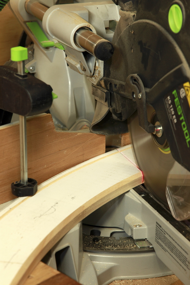
| The right hand end of the piece can be a butt cut, but the left hand end has to be cut with a 14-degree miter. | 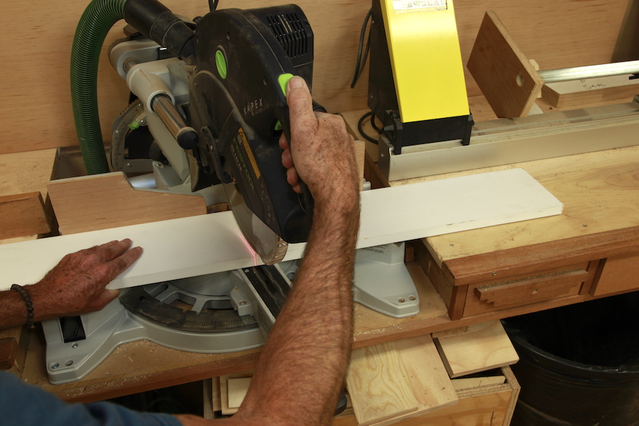 |
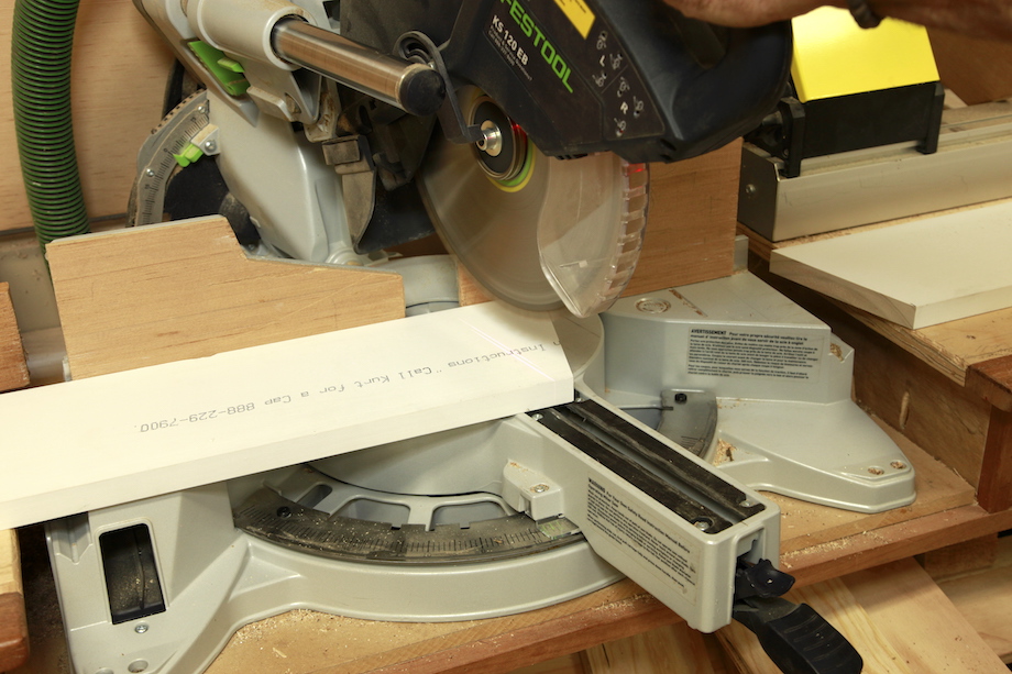 |
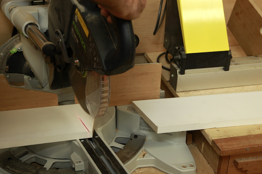
The center piece has a 14-degree miter cut at both ends and measures 13 1/16 in. from short point to short point. To cut the miter on the right side, I leave the saw at the same setting (especially if it’s some strange miter angle,) and just flip the piece over. |
| Then I measure and cut the piece to precise length. | 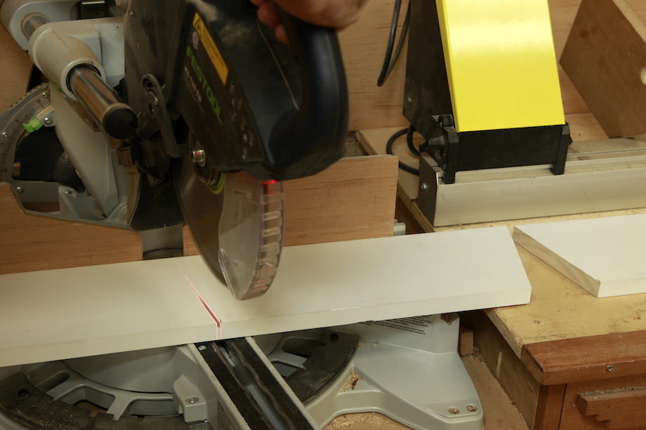 |
 |
The left hand piece is a mirror image of the right hand piece, but once again, I flip that piece, too, so the saw always stays at the same angle. That’s the best way to make sure the miters are grain matched—which is important for stain grade work. |
Of course, I always move the material through the saw in the same direction, too, toward my right.
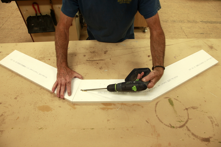
Pocket Screws. I add a pocket screw into each connection, right in the middle of the miter, so I can temporarily hold the three pieces together tightly on my table while I mark the blank for domino tenons. I put the pocket screws right near the middle of the casing so that I know there’s no way I’ll ever risk running into the screw with the router………. or a domino cutter.
Domino Tenons. I wanted to install some domino tenons in the joints of this casing, but I didn’t want to run into those tenons while routing out the radius casing. I went back to my big drawing board and temporarily attached the three-piece blank with a couple of clamps, setting the center of the middle piece right at the intersection of the center line. I slid and rotated the blank around that center line, and lowered it until I was satisfied that it was placed evenly to my drawing.
| Using the pencil trammel, I quickly marked the OR and IR of the casing. | 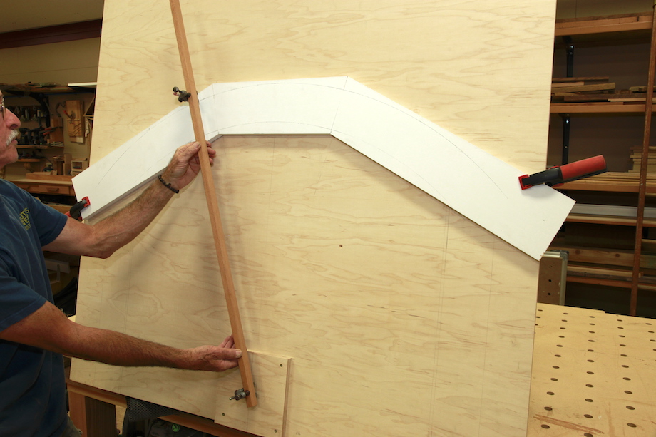 |
| I measured in from the radius marks one inch—which would be the center line for each domino. | 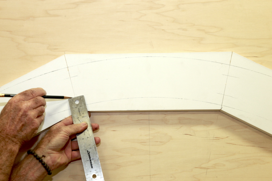 |
| Before removing the blank, I marked the bottom edge so I could replace it in the same location. | 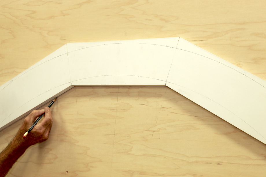 |
| After the mortises are cut, I reassemble the blank with glue, dominos, and the pocket screw. | 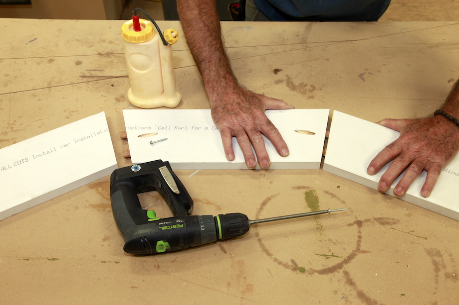 |
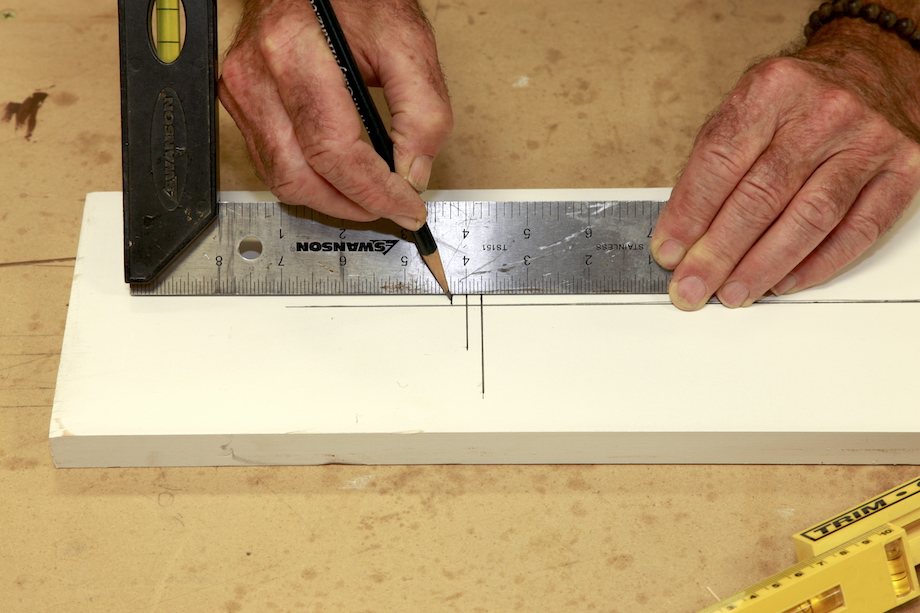
Routing. Now the blank has to be secured to the worktable for routing, and that means screws. And those screws cannot be driven through the front of the blank—they have to be secured from the back. Once again, I use my trammel arm to mark a center line for the screws.
Drilling pilot holes through the worktable makes it easy to hit the precise mark with each fastener.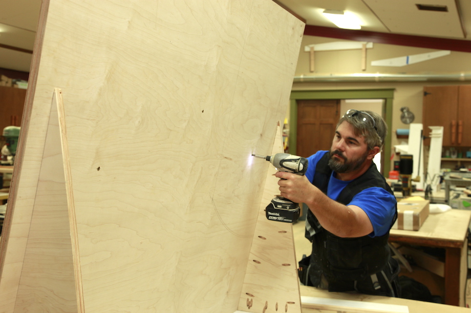
Cutting the blank and legs to length
Since the radius casing needs to be cut exact, I like to cut it first, then cut the legs to match the head casing.
| The easiest and most precise method (with the least amount of steps) is to grab a scrap of casing leg, hold it in position on the full-size drawing, and mark both sides of it, extending the lines past the head casing intersections on both sides. | 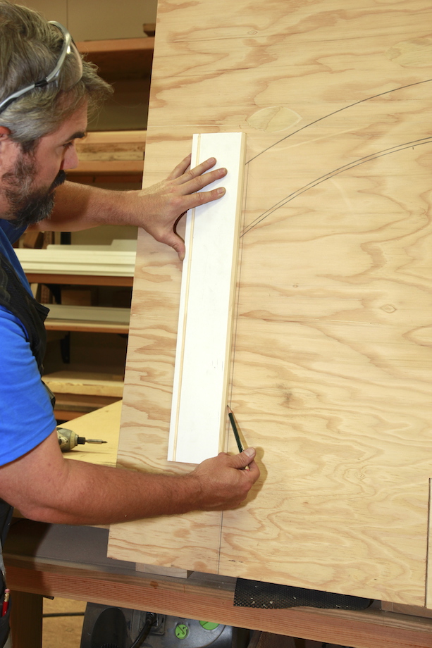 |
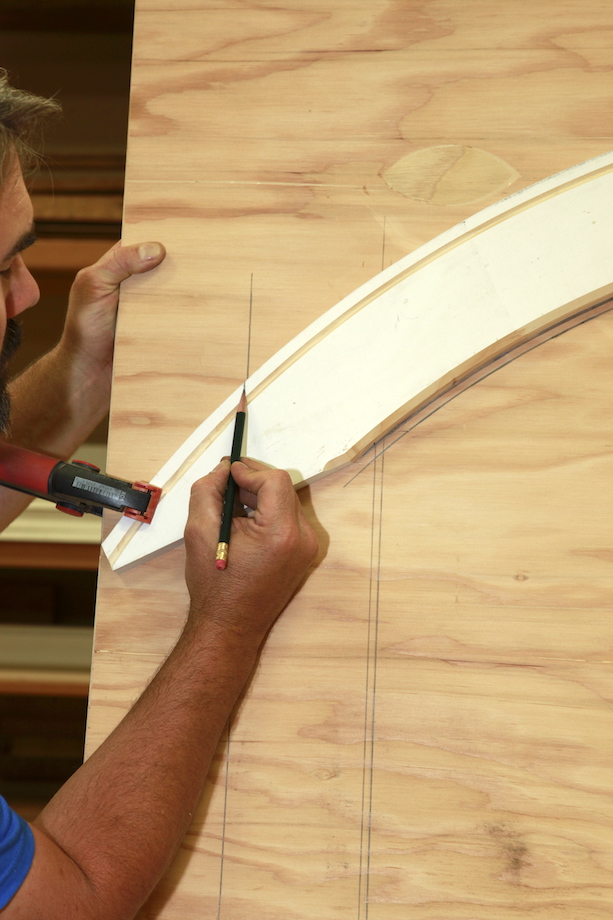 |
Next, I place the head casing back on the drawing and mark the points where the leg casing and head casing intersect. |
| I transfer those pencil marks to the face of the casing so that they’re visible at the miter saw. | 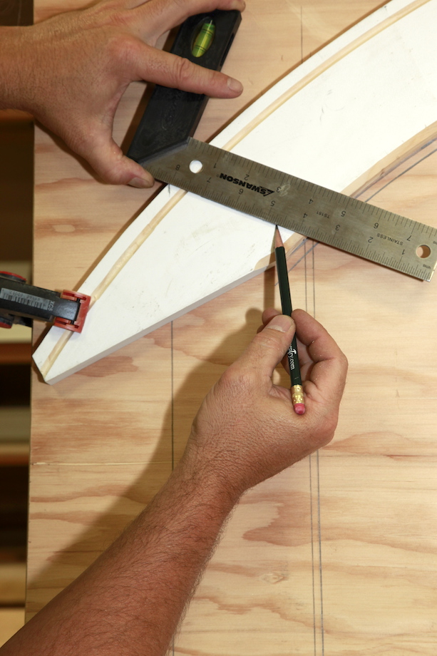 |
| After swinging the saw into a guesstimated detent, I hold the casing on the base of the miter saw and rotate it until the blade lines up with the pencil marks, and clamp down the casing. | 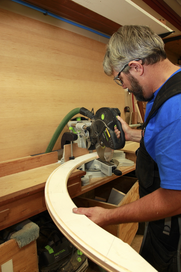 |
 |
Sometimes I rotate the blade a little bit, too, to get the marks on the casing to line up perfectly with the blade. And, with longer casing, you’ll do yourself a favor by having a stand or sawhorse behind you to support the other end of the casing while you set up the saw. Duplicate the process to cut the other end. |
| I cut the legs the same way, marking the intersection points. I often have to make slight tweaks to get those miters air tight, but it’s much easier to tweak the leg miters than the head miters. | 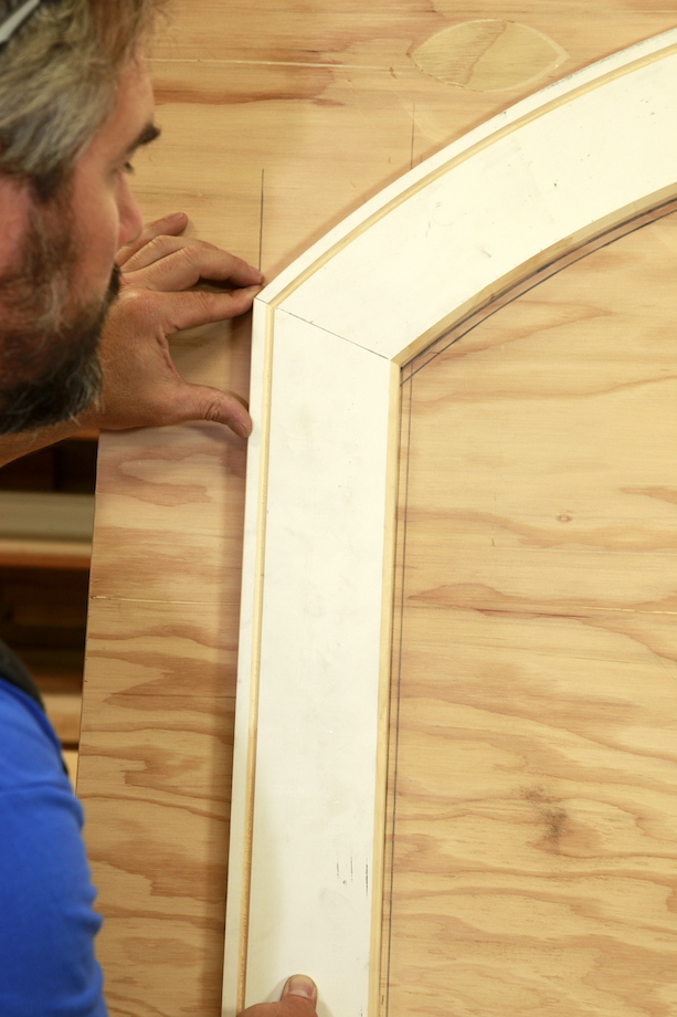 |
 Of course, sometimes you can skip those miters and use a radius head that is proud of the leg casing—which in my opinion looks a LOT better!
I know, I know, this article makes the whole process seem complicated, but…that’s the system I use and it freakin’ works!
How much time do you allow in a bid for this process?
How much time should I allow the first time I do it? Assuming the proper tools and so forth. Thanks in advance, WD
W.D.,
That’s a tricky question. I feel like there’s too many factors to have one standard time allowance for a bid. Ultimately, I like when a project has a bunch of radius heads because I can set up and repeat the process over and over…..and produce these heads fairly quickly. But, if I’m only making one head (and I don’t have to also make the legs), I’d like to give myself at least two hours of uninterrupted time. If you’re doing this for the first time, I’d bump up the time required to a 1/2 day, because you are going to tend to double and triple check every move that you make. And, you should double check, anyway. It helps to cut down on expensive fire wood. :)
Many window manufacturers will provide matching interior trim and jamb extensions in most any configuration , they will typically provide straight lengths also. Some are segment cut, more suitable for painting and laminated, suitable for staining. These are never cheap but with a absence of qualified field labor may be a viable solution.
Forgot to add, this is a real field time saver for elliptical units.
Nice article; excellent detailing of every step.
I use old Lady Cross (no pocket clip) mechanical pencils in my trammels and my scribers. Saves a lot of grief when you break a lead –– just twist out some more! Especially helpful with scribers, since sharpening the lead of a wooden pencil reduces the distance between the arm tips.
Always tip the trammel as you swing it so that you are dragging the lead slightly. This helps prevent lead breakage.
Older mechanical pencils are more suited to carpentry than the modern ones, which use skinnier lead. Even the .9mm ones are a bit too skinny.
********
An old FHB tip from the early 80s showed how to saw two pieces of molded trim into thin strips, offsetting the cuts so that the strips from one piece would fill in for the wood lost to the table saw on the other. Never tried it, and I’m sure that it made for a tricky glue-up to get everything flush. Sounded like a good trick, though.
********
I came ups with an easy, quick cheat on an old Victorian in which the existing trim in the house was 1x side casings, 5/4 heads. I divided the arch into three sections, using a piece of 5/4×8 for the “head” to sit between two pieces of 1×8 for the “side” elements.
I jigsawed the pieces to the rough radius, then used my antique Stanlley #113 radius plane to smooth the edges, taking special care to achieve the proper reveal. The job went very quickly, and the finished product looked great.
Thanks, Harlan. I would love to find myself one of those radius planes! And, you’re right about the mechanical pencils that we get these days…..
I had a similar task 6 or 7 years ago. The client wanted the effect of a transom over their front door. They wanted a match to their casing but in exterior material format. I had to create the calculations for the arch for the manufacturer of the polyurethane based trim, then give the mirror company the exact dimensions, they go through what you did, with a 10′ run. It was heart stopping getting the mirror up, but in the end, the client loved it. I used the same calculator and router extensions.
Cool Article Scott. This should be in the new category “How it’s really done on the job site” that Clayton DeKorne mentioned in the Facebook group Building Knowledge.
Thank you, Sim. That’s a great idea.
Awesome article! Time to get some trammel points.
you make it look simple . i want to go down to my shop now.
The problem is that most houses do not have flat stock for trim. I have never seen one. A good millwork place can make curved trim in any profile. I put back curved three piece trim matching the existing trim on an old house. I have a Viel machine to cut my own knives. There are lots of companies that can make custom knives for you. I have a Woodmaster planer/molder which I used to make the moldings. All of the math in the article can be used to cut the trim and guides for the molder. If you have minimal Algebra skills there is a formula for finding the radius of an arch without a calculator. Here is my story of putting back pocket doors with curved trim.
https://www.flickr.com/photos/31300792@N08/8356086137/in/album-72157632455995339/
Dan,
Thanks for reading the article. It was about making radius casing on the jobsite – when the casing is flat. Where I live, most new homes are designed with a contemporary or modern theme. So, we end up using a lot of flat stock trim.
You bring up a good point – a lot of homes don’t use flat stock casing. NOW WHAT?
That will have to be a different article. Thanks, again.
I use almost the exact same methods for all the radius trim I make! I have a woodmaster, shop fox and a hussey but it all starts with careful measurements on site! You can make a good side living just making curved molding if you measure everything properly and do all the steps like you mention here!
Nice work, Matt!
Pic2
Nic article Scott! What are your thoughts on ripping, gluing & laminating strips of stock to make your blanks? It’s more work but when making casing that is to be stained I like that the grain follows the arc.
In the same breath – I plan to use your method next time to compare results and time involved. I do love the challenge of making curves in wood!
Rich Dunlap
Centerburg, OH
Richard, I think laminating strips together is a great idea and a necessary technique if you have to produce a casing that has a tapering profile with details.
Thanks for reading the article.
The formula that the calculator uses is:
((Base length/2)squared + height squared)divided by 2x the height.)
This gives you the radius length of the cord.
I found the formula in an old carpentry book and have been using it and teaching my guys how to use it for years. It comes in handy all the time !
Steve
This is the way I was taught and it works great. I am a younger fellow but prefer to do things without the calculator. No offence to those who do, but I feel like I’m cutting a corner when I use one. The same goes for rafter layouts and stairs for me. There is something fulfilling about doing the math on your own and then putting it to the wood. Yes I know that time is money, but practice also makes perfect.
A fascinating product I stumbled upon recently might be good for this – http://www.puretimber.com
Wood you can easily bend! The demo videos are pretty mind blowing and if it’s even half as good as they claim it’s amazing.
Great article! We recently did a job with a lot of stain-grade radius trimwork and found that cutting our miters with Festool’s newer HKC crosscut tracksaw was very efficient and accurate. It eliminated the awkwardness of propping up material and fussing with the angle on a miter saw because we could just cut trim on sawhorses where it was going to go (most casing heads were 8′ long so this was particularly helpful). A good sharp blade and cutting pieces upside down helped ensure there would be no chance of tear-out on the showface.
Just to add onto the tracksaw.
I recently trimmed a circular window. A local shop specializing in interior curved mouldings made them up as 2 separate pieces. The tracksaw spanned all the way across the window making it really easy to get 2 perfectly flat cuts. I can’t get enough of the tracksaw for trim carpentry now that I have it!
What a great idea. I bet you made a couple of practice cuts before cutting your actual piece. Thanks for reading the article.
I guess it’s official now: I’m an “old guy”. Great article, none the less.
Craig
Ingenious work.
I frequently use trig to determine angular dimensions of raked pony wall caps to calculating entire roof sections, this is primarily because the first building book I read was Marshall Gross’s “Roof Cutting” and he is a proponent of using trig for all angular calculations. When I read this article I got excited because I knew then there was a way to determine angles and a radius within a circle without a ton of guesswork and experimentation. Unfortunately I could fine no video explaining how to use trig to find the radius of a circle using only the cord and the perpendicular bisector. 6 days later, a job site goof-up, and a couple conversations with my mathematician friend, I’ve found a quick formula for the calculations using trig.
1. (Half of cord length/perpendicular bisector) x arctan
2. 180 – (Theta (from step 1) x 2)
3. Half of cord length / sine(theta from step 2) = Radius
Once you know theta from step 2
Theta x 2 = arc angle
(Arc angle/360) x (2 x pi x r) = length of arc
Thanks for the article, I’ve got a house full of arched windows to trim out and this article gave me a solid attack plan so I’m not just throwing trim on the wall hoping that it sticks so to speak. :)
Josh,
I’m glad you enjoyed the article. I’m pretty certain that you’re way ahead of me when it comes to the trig. The calculator saves my butt on this type of work. Good luck with your upcoming project.
Scott