


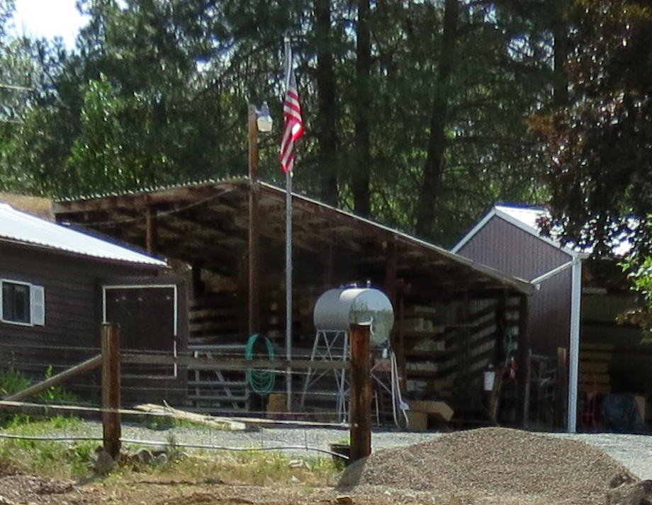
One of my customers needed to keep his new tractor and hardwood slabs dry. He had this old horse barn or stable and wanted to remodel it. Calling the dilapidated pole structure a ‘horse barn’ gives it too much credit: It had metal siding on only two sides; the roof leaked like a sieve and was open on the tall side—nearly 15 ft. high and on the nasty north side! The poles were more than a foot out of line, two feet out of square, and you don’t even want to know how far out of plumb, but I’ll tell you anyway—one of them was out four inches in 10 ft.
(Note: Click any image to enlarge)
We had been using the structure as a temporary storage shed for ongoing projects. It was loaded with miscellaneous dimensional lumber, some BCI joists, stacks of WindsorONE moldings and boards, and even sheets of PVC. You get the picture—the kind of place where you always leave a plugged-in circular saw ready to go. Of course, the tall leaky shed roof on this barn never bothered the horses or the hay storage, but it wasn’t going to keep my client’s brand new Kubota tractor and eight quarter hardwood collection dry for long. If this isn’t a story about turning chicken poop into chicken salad, I don’t know what is! (And in case you didn’t already put it together, this chicken poop belonged to Gary Katz!)
Cut poles to height
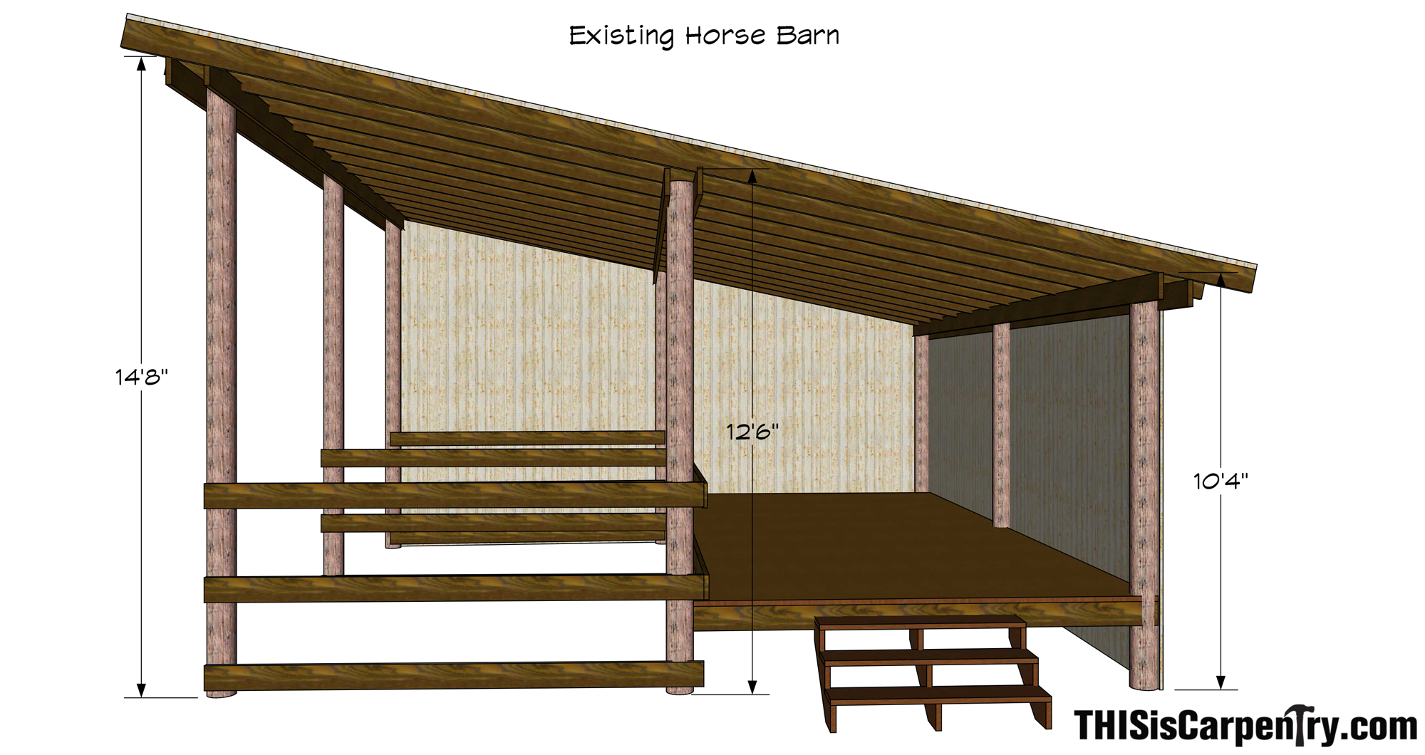
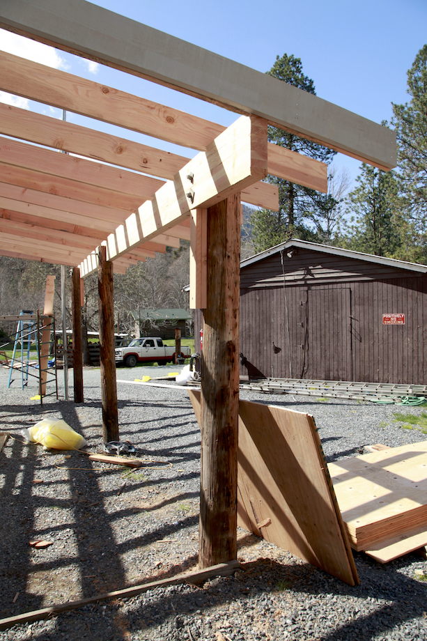
The only thing worth saving on the whole roof structure were the support poles and all of the heavy duty galvanized bolts, nuts, and curved washers, so the first thing we did was tear off the metal roof, cut out all of the purlins, and expose all of the poles. The plan was to convert the existing shed roof structure into a low sloping gable roof. I started by setting up a laser level to help determine which poles were the shortest in each row. We decided to leave the height of the center row of poles alone and simply cut them level to the lowest of the three. We did the same with the south row of poles and cut two of them to match the shortest of those three. Then, we cut the north side poles to match the south side, creating an equal pitched roof…well, almost equal.
String-lines for parallel
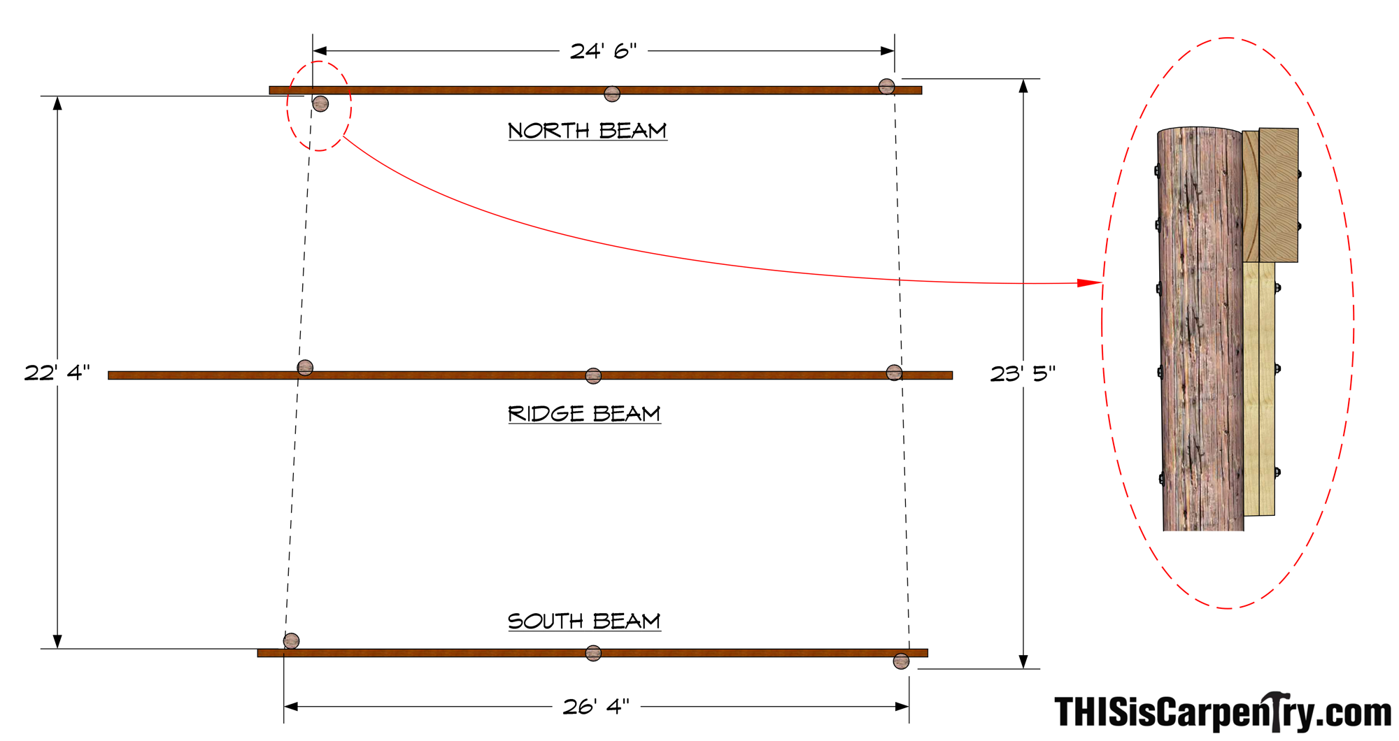
Cutting the poles to the right height was the easy part; the next step was solving the hard part. None of the poles were in a straight line in either direction. I had to figure a way to attach 4 x 12 glulam beams to the uneven poles and keep the beams parallel. The alternative was to ignore parallel beam lines altogether and set each glulam as in-line as possible on each respective line of poles. However, if I did that, I would have to custom cut each rafter on both sides, and I’d end up with weird rooflines, and out-of-square fascia. That’s no fun!
The first thing I did was pick the side with the straightest line of poles—the south end. We ran a string line as close as possible to center across the three south poles. Since there really was no center, we moved the string around until we were able to find some bearing on each pole.
| We notched the center pole right in the middle; the pole on the eastern corner we notched on the northern side; but the pole in the southwest corner was so far out of line we had to bolt 2x backing to the side in order to support the glulam. | 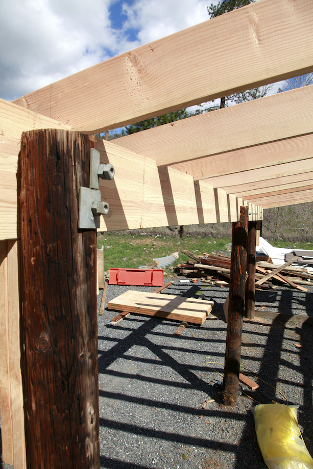 |
After that, I set a string on top of the center line of poles and made the string parallel to the south string line simply by measuring with a tape measure. Both the center and the north pole were somewhat inline, but once more I had to add blocking to the west pole or there wouldn’t have been any bearing for the glulam.
 |
And on the north side, I had to block both the east and the west poles, on opposite sides! I figured my client’s shiny tractor wouldn’t care how the framing looked as long as the roof didn’t leak. And besides, there was no way we’d move any of those poles—they were set over 6 ft. deep! |
Notching the poles
I left the strings up until all the notches were cut so that I wouldn’t get confused and notch the wrong side of a pole.
| The glulams were 12 in. tall so I measured down 9 in. from the top of the poles that we had already leveled. In case a rafter landed directly above a pole, I let the beams stand 3 in. taller than the tops of the poles so that the rafter tails would fly past the tops of the poles. | 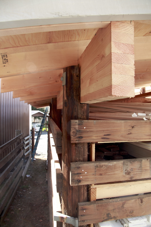 |
As I’ve already explained, in several cases, we bolted the beam to the poles without any notch.
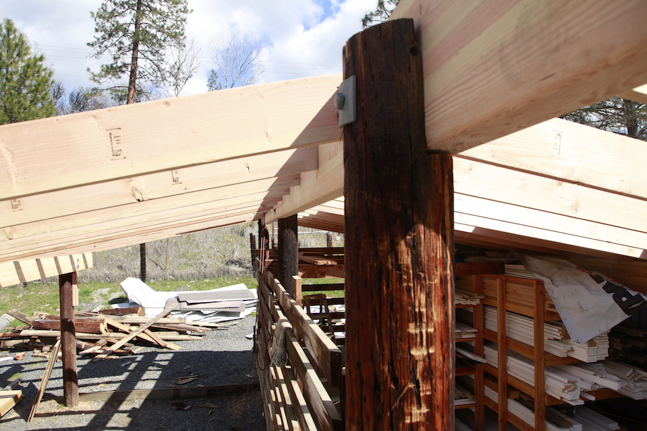
Setting the beams
The glulams for the north and south sides were 32 ft. long, and the glulam we used for the ridge was 38 ft. long. I ordered the extra-long glulams because I knew we’d want to extend the beams out farther than the poles so we could square up the roof. And my client mentioned wanting to maybe create a big prow on the front of this building, to match the prow on his 40 x 60-ft. shop. Between the Kubota tractor and a rented Genie lift, we were able to place all of the beams into position and get them bolted tight.
Find square for rafter layout
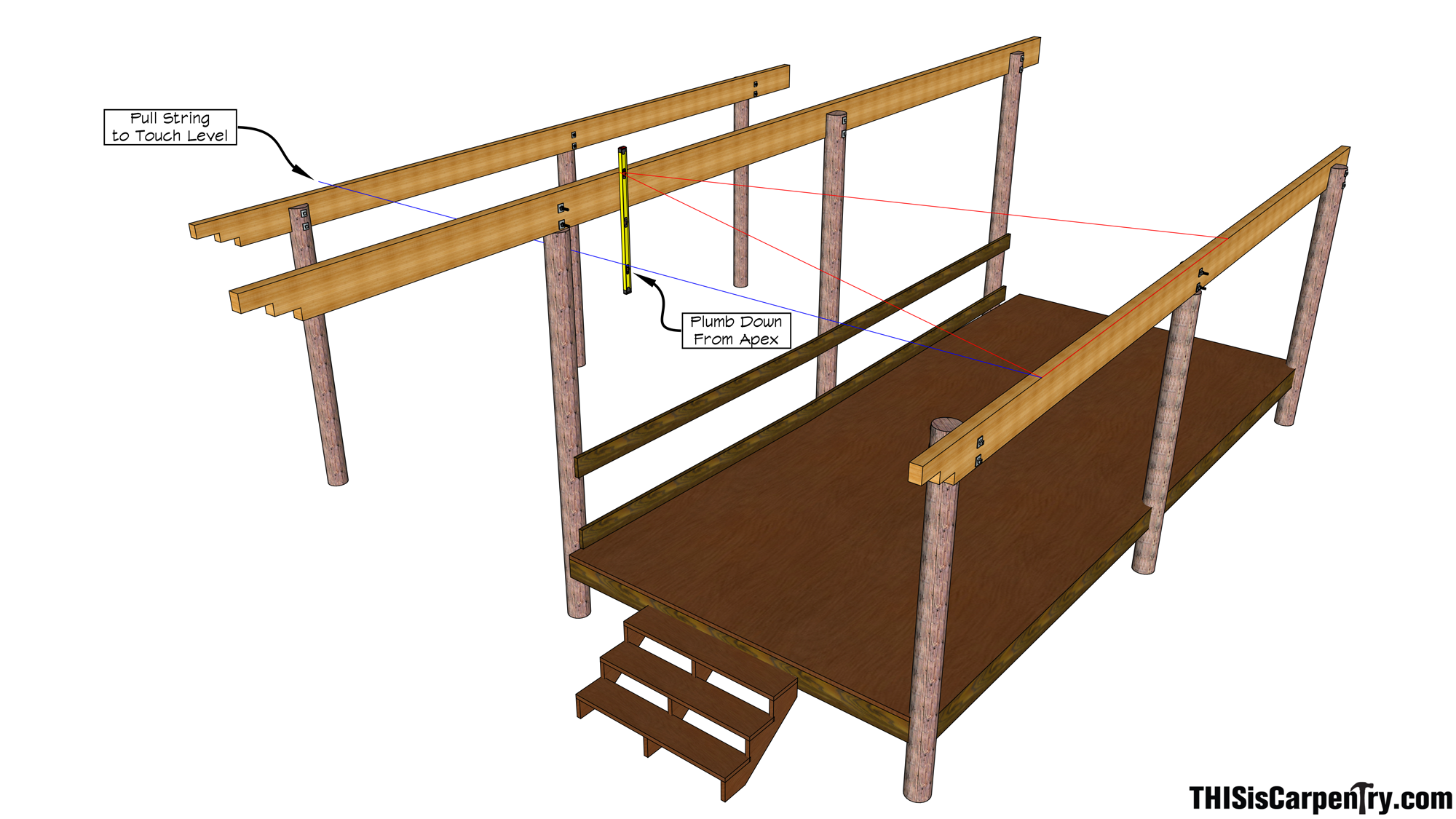
After adding a couple of braces to straighten out some of the bows in the beams, finding square for layout was fairly simple because we had done an adequate job of placing the beams parallel. I wanted to pull measurements from the south beam to the north beam and calculate the diagonal to find square, but there was too much interference from poles, our catwalk, and my client’s extensive lumber storage—which we did not want to move. So I came up with a workaround—literally.
First, I made two pencil marks 12 ft. apart on the south beam and simply measured the distance on the rake between the south and ridge beam. Next, using a Construction Master Calculator, I entered a 12 ft. “RUN” measurement, the raking measurement as the RISE—12 ft. 4 1/8 in., which I measured by arcing my tape along the ridge. Then I calculated the DIAGONAL—17 ft. 2 9/16 in. With my helper holding the dull end of the tape on the south beam line at one of the pencil marks, I stretched the tape out along the edge of the ridge beam until the DIAGONAL length intersected it. Once the intersection was clear, I had a point on the ridge beam that was square with the first pencil mark on the south beam!
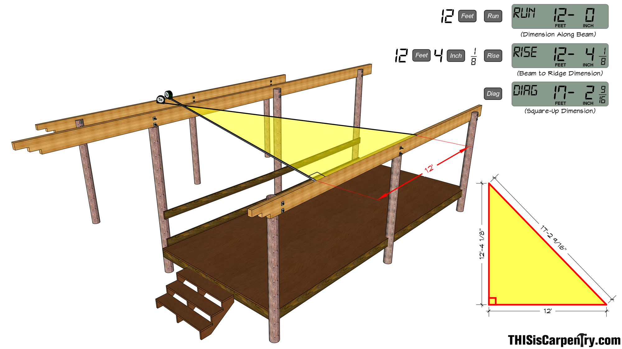
Finally, I pulled a string from the pencil mark on the south beam all the way to the north beam and swung the string side to side until it was directly plumb beneath the mark on the ridge beam (Step #4). Now I had a reliable benchmark on each of the three beams that could be used to layout for rafters.
Calculating the commons
I decided to install the rafters so that the plumb cut on the rafters would plane into the top edge on each side of the ridge. Even though all of the little birdies flying around Gary’s house are cousins to chickens, I couldn’t let them get too cozy and comfy in a new nest that they’d undoubtedly be building on the little shelf created by setting the rafters on top of the ridge. Besides, at this point, we were going for a particular design.
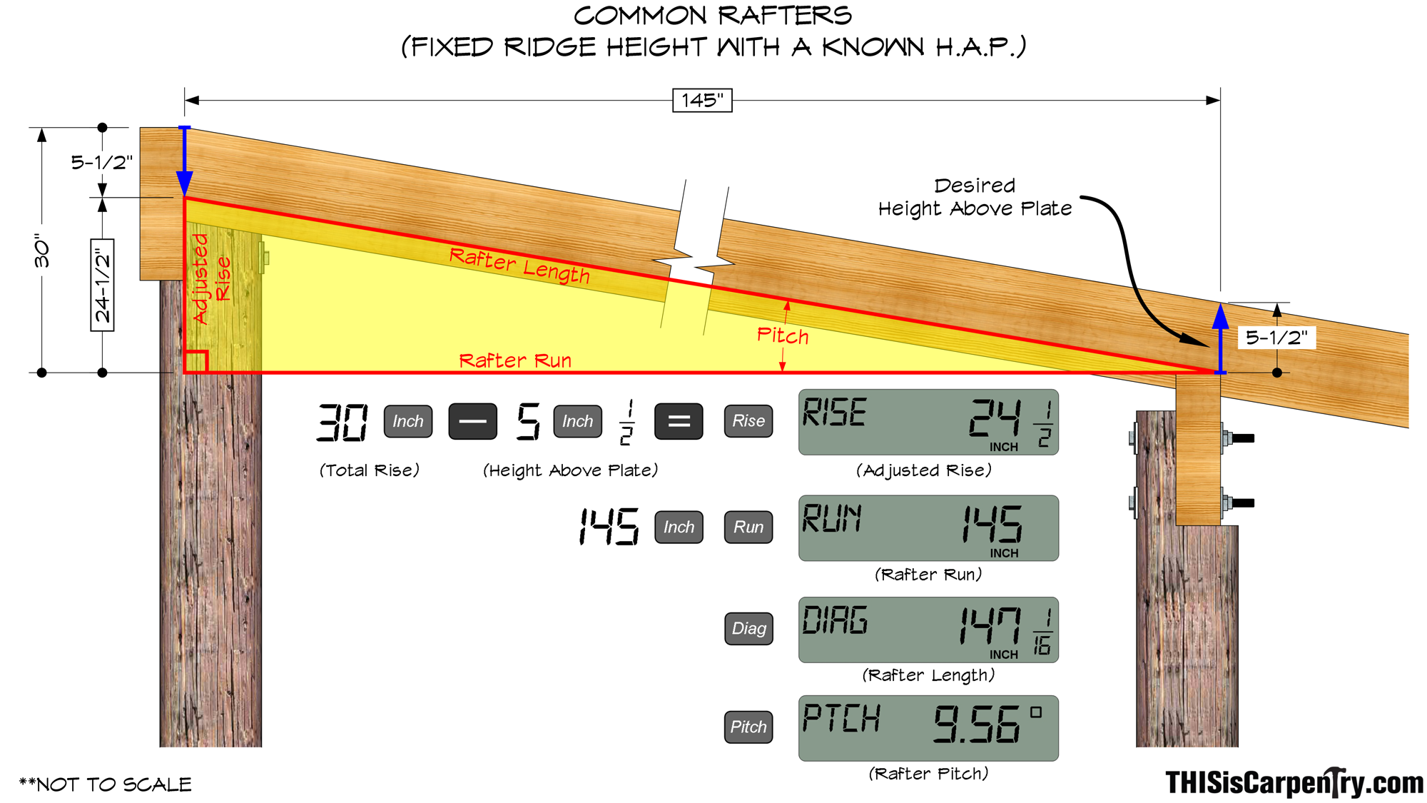
It was obvious that this was going to be a very low slope roof. To increase the pitch—at least a little—I cut an extra deep bird’s-mouth notch at the lower beams—2 in. deep (yes, that meant a notch and not a standard seat cut!).
Using a level to plumb down at each side of the ridge, then measuring back to each lower beam, I found the two horizontal spans for the common rafters were off by three inches, with the North span being shorter, which meant two different calculations for the common rafters. The difference in the two spans would be indistinguishable as far as the plumb and level cuts on the rafters, and wouldn’t be noticeable to anyone looking at this chicken shi…I mean lumber shed, anyway.
Since the ridge beam was already set at a fixed height, I had to work backwards in order to determine the pitch and length of the common rafters. In this situation, I wasn’t shooting for a specific seat cut length—I was more concerned with increasing the pitch of the roof. So I decided to reduce the 2×8 rafter’s height above the plate (HAP) to 5 1/2 in. and cut a notch instead of a standard bird’s mouth. Since I had already measured the ‘run’ of the rafters, I only needed one more number—the rise—to calculate the pitch. To determine the rise, I stretched a string from the north beam to the south beam, passing right under the ridge, then measured from the ridge down to the string, which gave me a total rise of about 30 in. With the HAP already determined, I simply subtracted the 5 1/2 in. from the 30 in. total rise to find the “adjusted” rise and made my final calculations for rafter length and pitch.
We were able to secure the rafters to the beams by nailing the rafters down to the top of the beams and adding a screw to the bottom edge of the rafters where they intersected the inside face of the beams. Had the rafters dropped deeper into the inside of the beams, I could have used a joist hanger to help support the rafters.
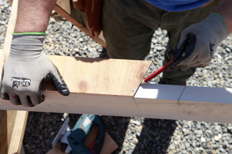
I placed all the common rafters crown down on a pair of beefy sawhorses and laid out the plumb cut at one end and the bird’s mouth at the other. I picked 24 in. for the overhang. Easy-peasy.
| The homeowner was in town while we were stacking the roof, not gallivanting across the country, so we finally had an exact length for the projection of the prow. |  |
Cutting the prow rafters
Gary said that he wanted the prow on the front of the building to really be pronounced. He wanted that prow to fly out there as far as the ridge beam would let us go. So we agreed to extend the prow rafters out 6 ft. beyond the last common rafter at the ridge, and set the lower end of the prow rafter directly above the last pole, which would leave about 3 ft. of ridge still extending proud of the prow rafters.
I always try to think of roofs as combinations of rectangles and triangles, and this roof was no different. After laying out the ridge for the location of the prow rafter, I worked some easy math with the Construction Master to calculate the length of the rafter itself.
Entering the common rafter length as the “RUN” and 6 ft. as the “RISE,” I pressed the “DIAGONAL” button. The result was the prow rafter length. Pressing the “PITCH” button told me the angle at which the rafter would intersect the two beams—the angle of the bevel cut.
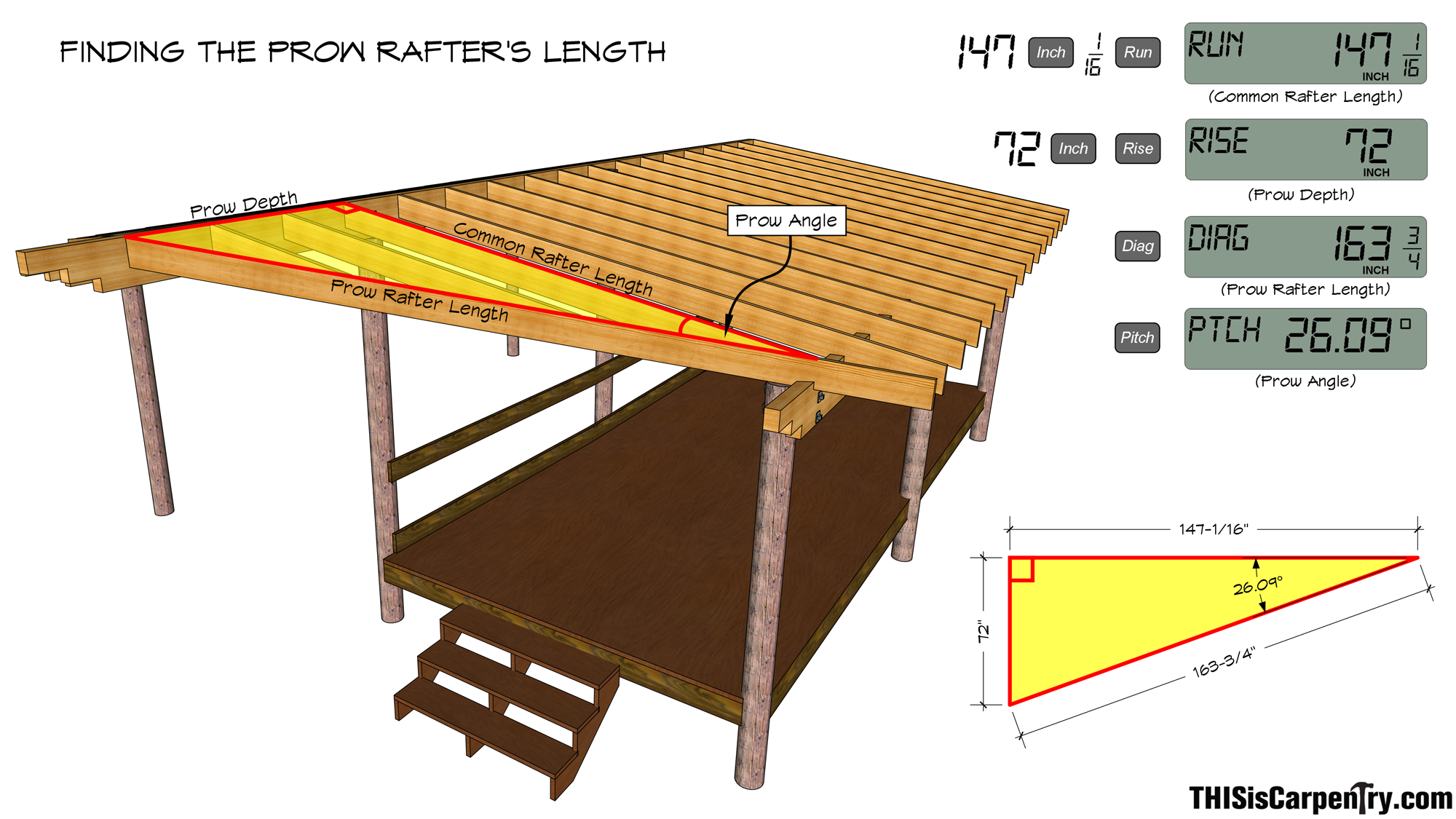
Still thinking in terms of right triangles, I entered the prow rafter length as the “DIAGONAL,” and entered the same “RISE” that was used to determine the common rafter lengths, then pressed the “PITCH” button again. This time the calculator gave me the angle of the plumb cut for the prow rafters.
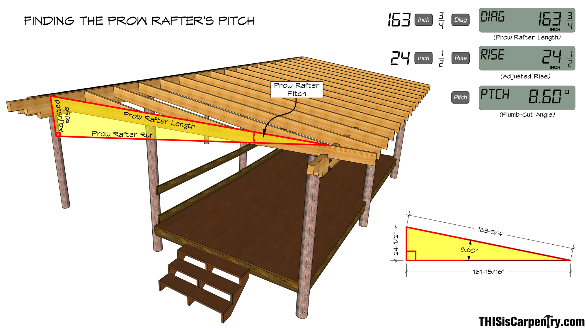
Of course, for anyone who has cut roofs before, those angles are the same for the bird’s mouth at the bottom of the prow rafter.
 |
 |
Notching the glulams
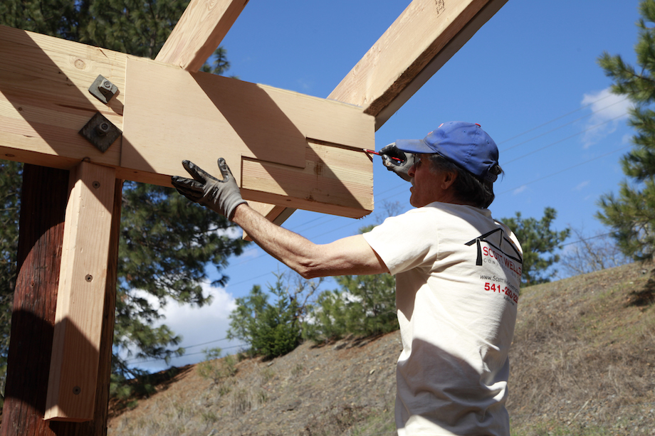
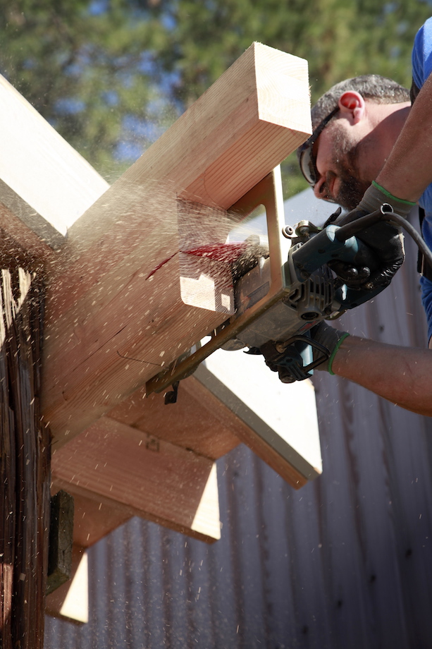
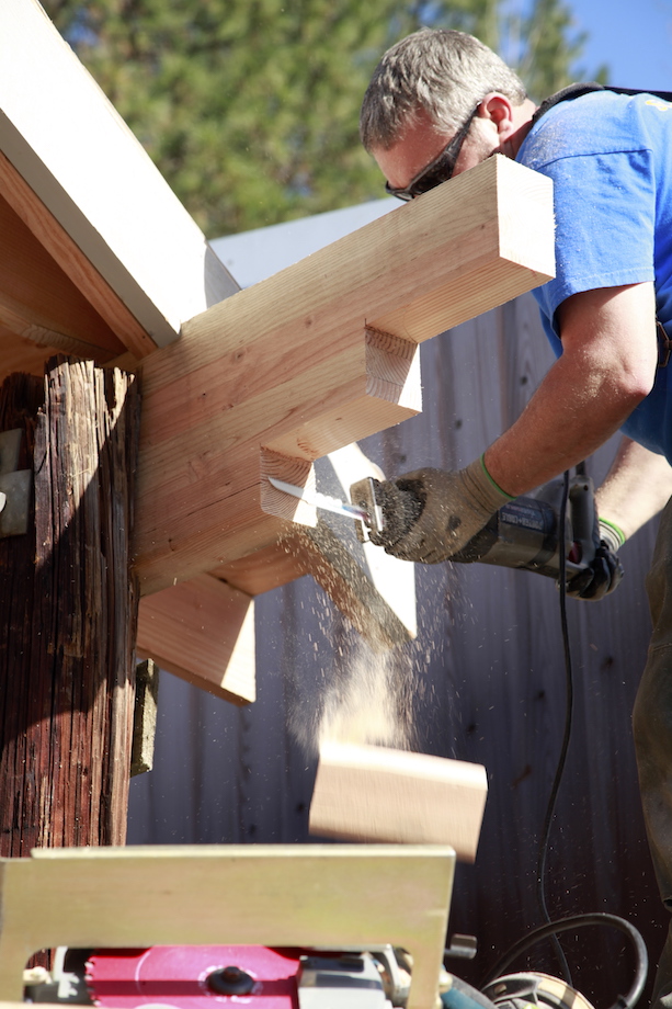
If you know Gary, you know he loves that three-step lift detail found in Greene and Greene homes. We came up with a balanced cloud lift pattern that we were able to cut into all of the beam ends. Darrell Peart refers to that three-step design as a waterfall pattern, which is pretty descriptive when you think about it.
After unsuccessfully attempting to cut the first one with a chainsaw (now THAT was Gary’s idea!), we fell back to real carpentry tools.
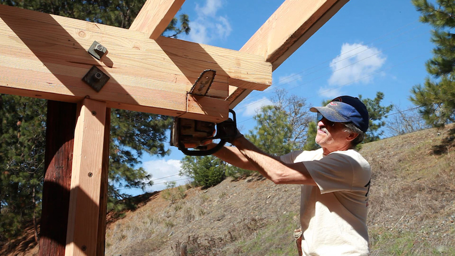
I used a 10-in. big foot saw, a regular circular saw, and a sawsall to cut each of the waterfalls.
 |
 |
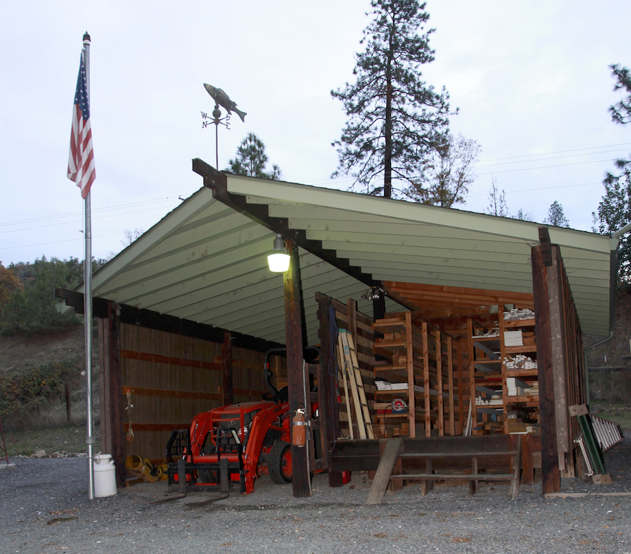
The finish
We stained and painted the new wood, added metal gutters, added siding that matches the rest of Gary’s buildings, and installed copper caps on top of all of the exposed beam ends to keep them from rotting.
When we finished—and I kid you not—the Kubota was bone dry, the hardwood was totally protected, and that old leaky horse barn looked like chicken salad.
Very well written as usual. I love the shots of Gary with the chainsaw! Who says a chainsaw can’t be a finish carp’s tool?
I totally agree, Tim. There’s definitely a time and place for a chainsaw on the job.
Lol, I called it when I saw new article. Has Gary been working on his barn again? Nice work on the old thing.
Thank you, David.
As I recall every “pick up” carpenter working for framing companies in Northern California back in the day through that a chain saw was just another tool in the tool box. We didn’t have the Big Foot other than the 16″ Makita 5402 that was occasionally available from some of the contractors. No the tool of choice for cutting out floor joist or other wise large dimension lumber was the Echo 302 with a 14″ bar. I still have mine. With a sharp chain is was a wicked wood cutting machine and with some practice would give an acceptable framing rough cut. Although he is retired now I used to look for any excuse to break him out and maul a bunch of lumber. Twas a fun article lads
Paul, I don’t see chainsaws on frame jobs very often, and it surprises me. It just makes such quick work of so many tasks on the job.
Good job with the chainsaw. Way to stay with the traditions of your new home. Keep this up and you will be a “local” in no time
I appreciate what you said about using rafters. That seems like it would provide good tractor coverage. I’ll have to update to a new model.