


Every now and then you get to do something really fun. One of my recent, fun projects was a dining room ceiling in a new private residence with a 1920s design theme. We ran hundreds of feet of Pickwick paneling in this home—complete with hidden doors to storage areas, and the wall switches were push-button.
The octagon ceiling consisted of T&G ash, 2×8 flat beams which rested on columns and met in the center, and 8×8 arched beams that originated at corbels mounted to the columns and also met in the center.
(Note: Click any image to enlarge)
| The first step was to install the pre-finished T&G ash on the ceiling. We laid out the flat beams and installed the ash so that the cut ends would be covered by the trim adjacent to the flat beams but would not interfere with the cradles we would use to mount the flat beams themselves. I had never worked with ash before and I was impressed with how hard the stuff is. | 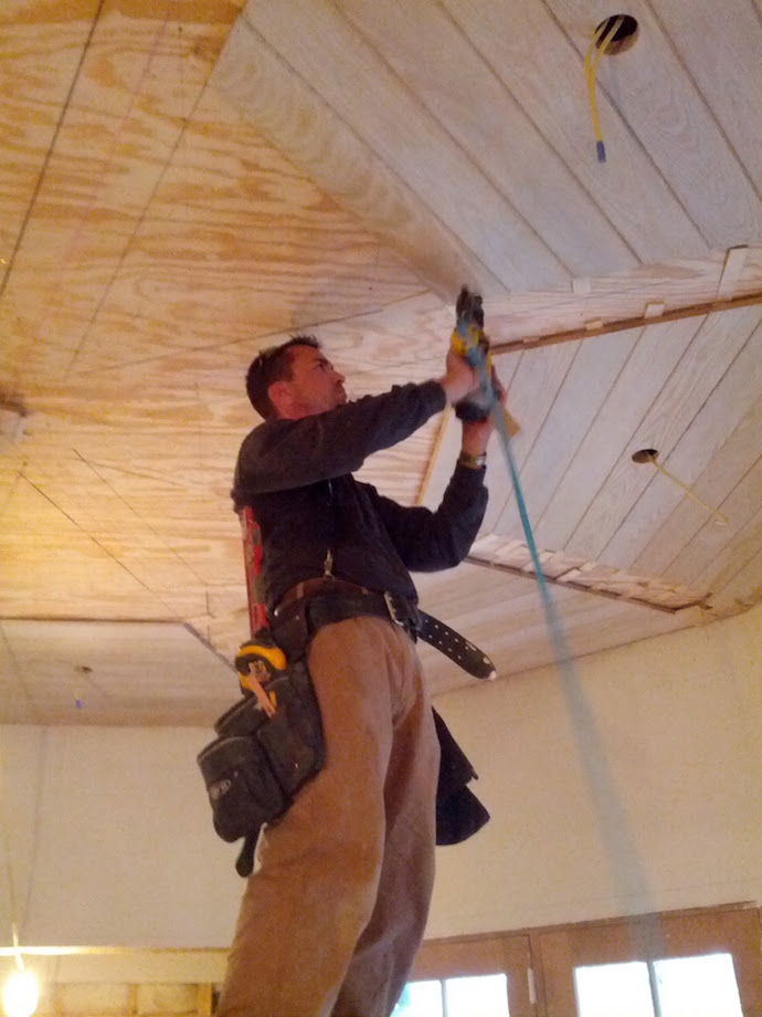 |
 |
The plywood ceiling was not perfectly flat, and we had a 1/2-in. reveal from the flat beam trim to the bottom surface of the flat beam. |
We chose an elevation for the ceiling that would allow us to install the T&G in a flat and level plane independent of the plywood, we ran strings in all eight directions representing this plane, and we shimmed carefully as we went.
| Here we’re installing the cradles for the flat beams. | 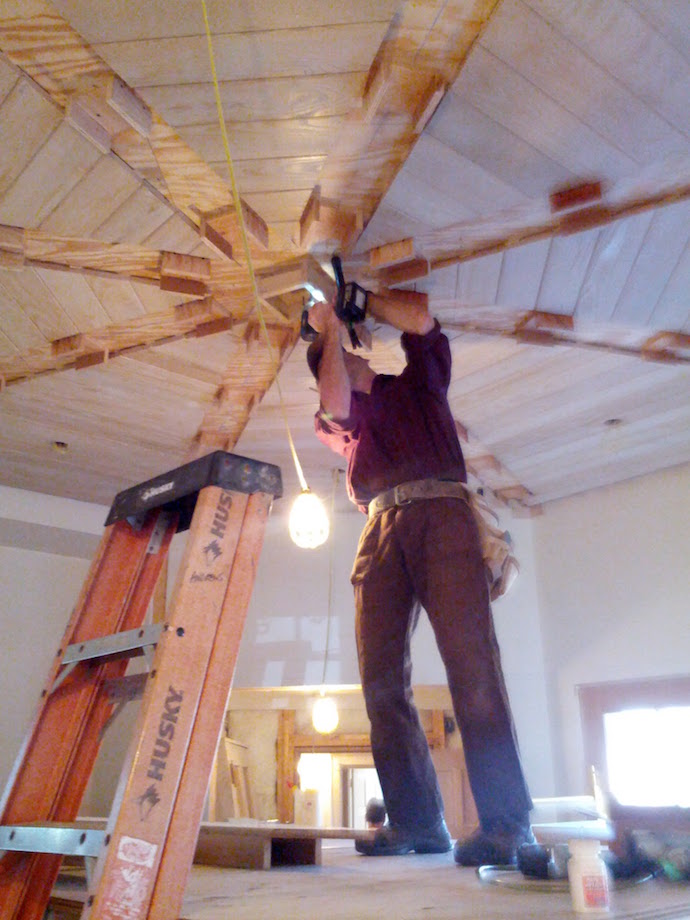 |
| We made these just slightly undersized in width and set them carefully to a chalk line. The layout is critical—if the geometry was not true, our angles would be off and the shoulders of the cuts would not align. | 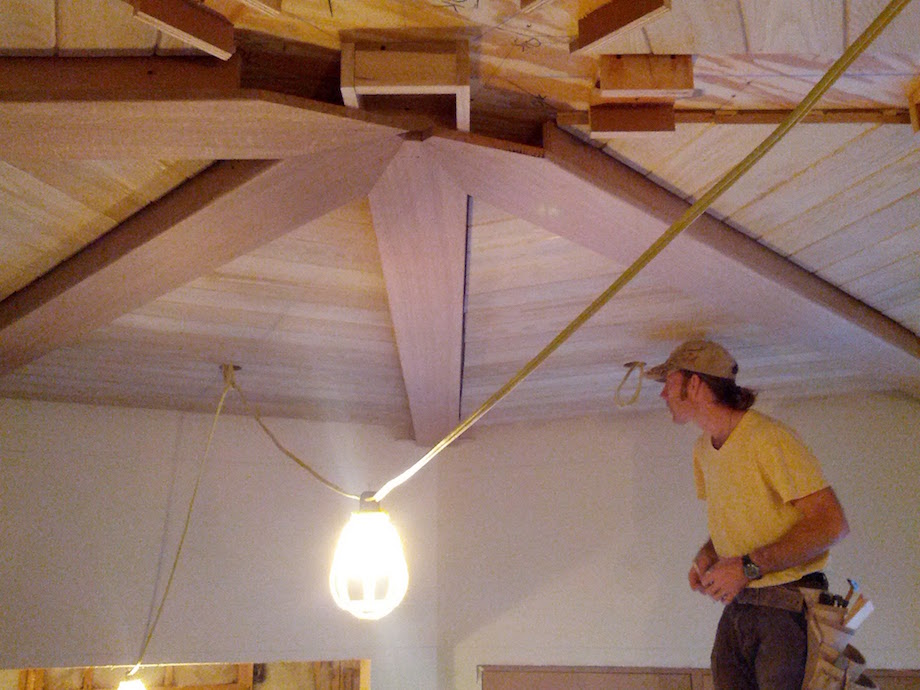 |
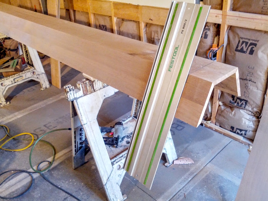
| This is the jig I made to cut the flat beams, which were QS white oak. Getting the miter dialed in required cutting several pies out of scrap. Once that was set, we dedicated the saw to this task. | 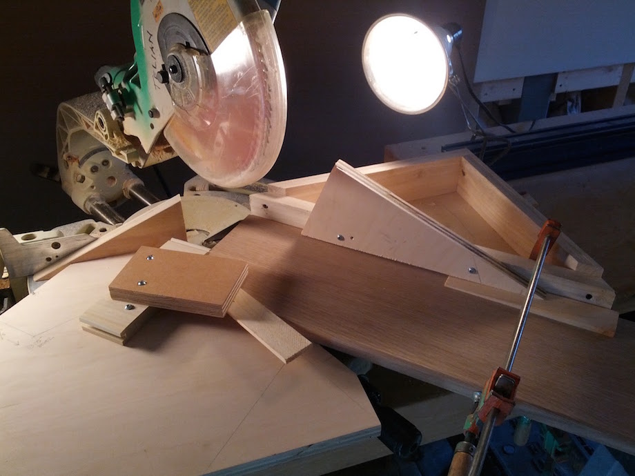 |
Every piece was clamped to the acute-angle jig, and shims were slid in tight beneath makeshift hold-downs to keep the stock flat against the saw base.
We started installing the flat beams. The back end could run wild as it would be covered by the column. Since the sides of the beams would be covered with the flat beam trim, we used MDO plywood biscuited and pocket-screwed to the face before installing the beam as a unit. Then we checked the fit and screwed through the plywood sides into the cradles.
We measured the remaining angle after installing each new beam, making sure we were progressing in accurate increments of 45 degrees.
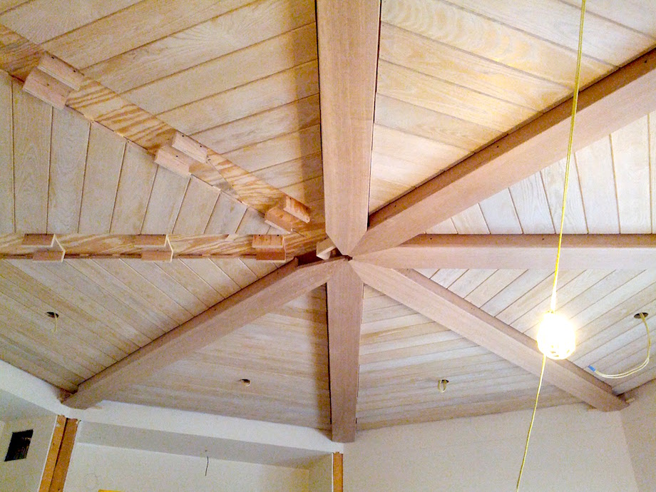
All eight flat beams were installed, and the end result was nice and flat. The roundovers required care—we could do most of the length of a beam on the ground, but the back end had to be done in place with a gauge to avoid routing beyond the front surface of the column and creating a mouse hole.
 |
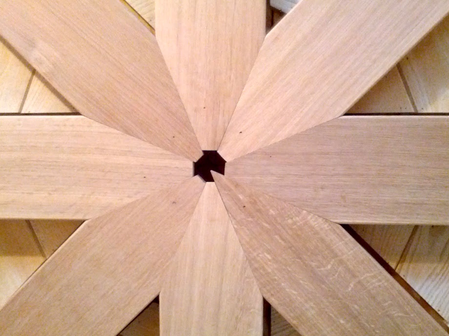 |
The joinery worked out nicely. Since this would be almost completely covered by the arched beams, the points of the flat beams could be nipped, with the exception of the first one which was used to locate the beam at the center-point of the room.
With the flat beams in place we were ready for columns. These came preassembled from the shop, and we only had to cut them to length and scribe them to the walls.
| In this picture, you can see that we snapped chalk lines using a laser and we installed our blocking. | 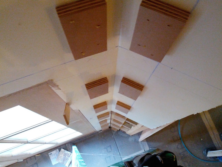 |
 |
Cutting column to length. |
| The columns had to be scribed fairly tight to the sheetrock which was going to receive wallpaper. The void at the back ends of the flat beams allowed us to shim them tight to the tops of the columns off a block on the wall. | 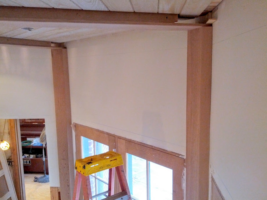 |
Once the columns were in place, we added the perimeter beams.
| This was mostly a simple matter of blocking and sizing the beams with stair gauges, but as you can see we had some difficulty attaching the top blocks accurately because of how close they were to the wall. | 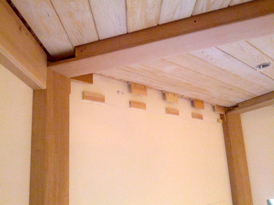 |
I suppose we could have just put a cleat in there and dispensed with the vertical block face, but I think we wanted more gluing surface.
We preassembled the perimeter beams onsite from solid stock.
| The pre-assembly made the fitting a bit more challenging, but it gave us a nice joint between the face and the bottom. | 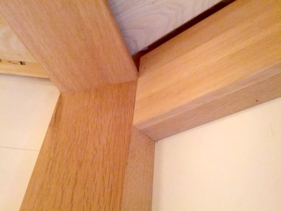 |
This is a simple elevation I drew of the room in order to calculate the corbel height using a given radius (top of flying beam) and a given chord length (column to column).
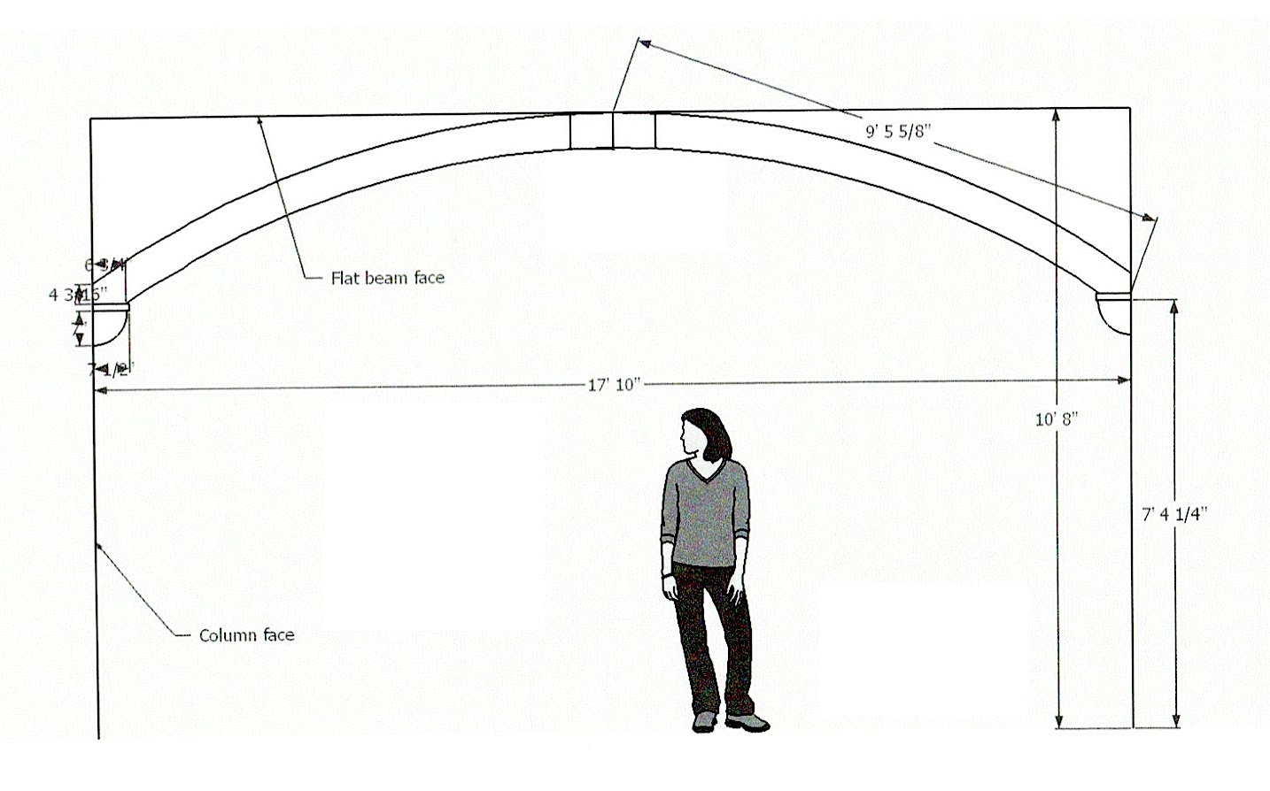
Sketchup is a really useful tool for these types of large-scale layout problems, because you can sketch the known geometry and then measure the drawing to get other useful dimensions—in this case, the approximate chord length of the flying beam.
 |
The arched beams were made from MDF with QS white oak veneer. |
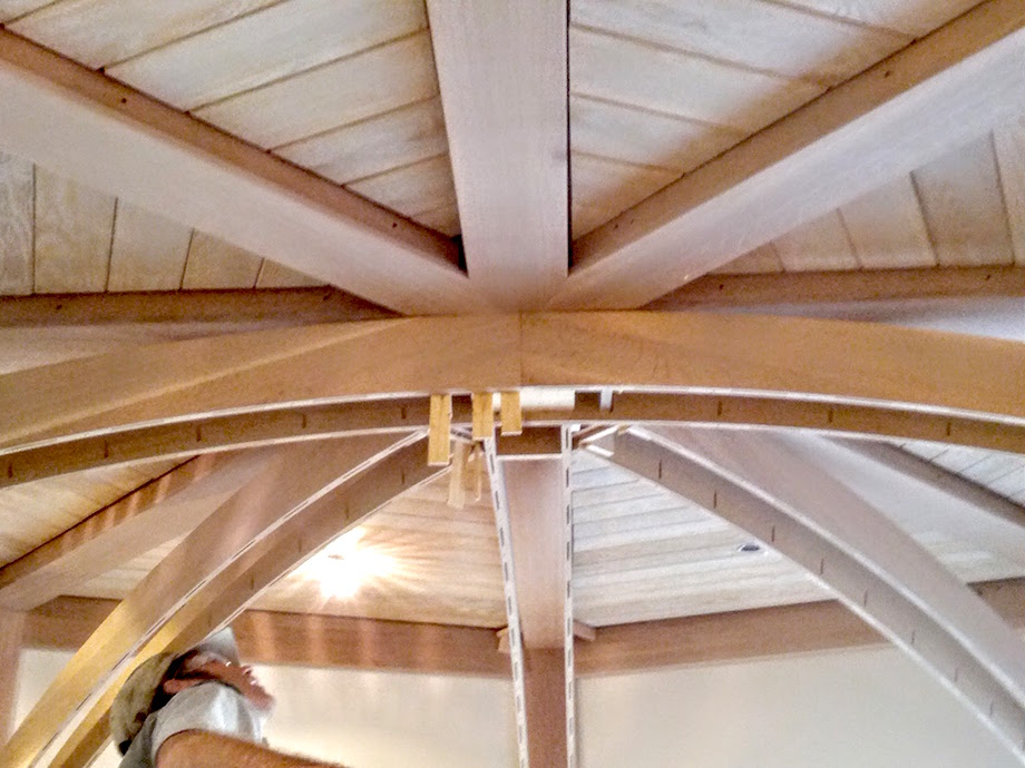
The arch was designed to just skim the surface of the flat beams, and the layout matched the flat beam layout. We installed each beam in four pieces to simplify the fitting—sides first, then bottom, then top (which was not visible and was really just a filler).
In the above photo, you can see the sides for the first pair we installed in the foreground, running “through.”
| The perpendicular pair butted into this pair, and then the other four were added to bisect the quarters. | 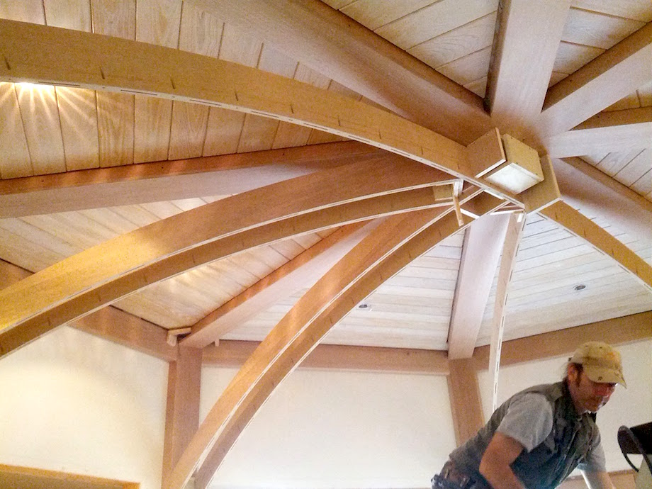 |
Below you can see the pocket holes used to fasten the bottoms to the sides, and you can see some of the blocking we used to fasten the sides together at the central intersection. In the background are pressure blocks holding the sidewall beams in plane with the columns while the glue sets.
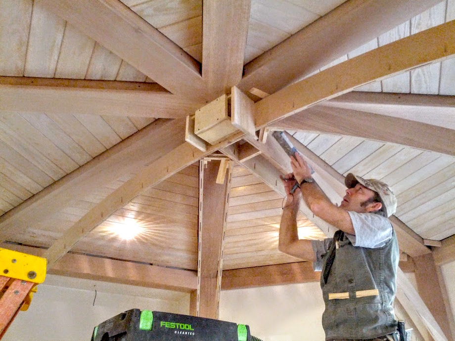
Most of the beam sides could be marked in place by holding the beam beneath its intended position and transferring a plumb line.
| The four beams bisecting the quarters were the hardest, but we worked out a fairly reliable method using a torpedo level and a piece of scrap ripped on a bevel. | 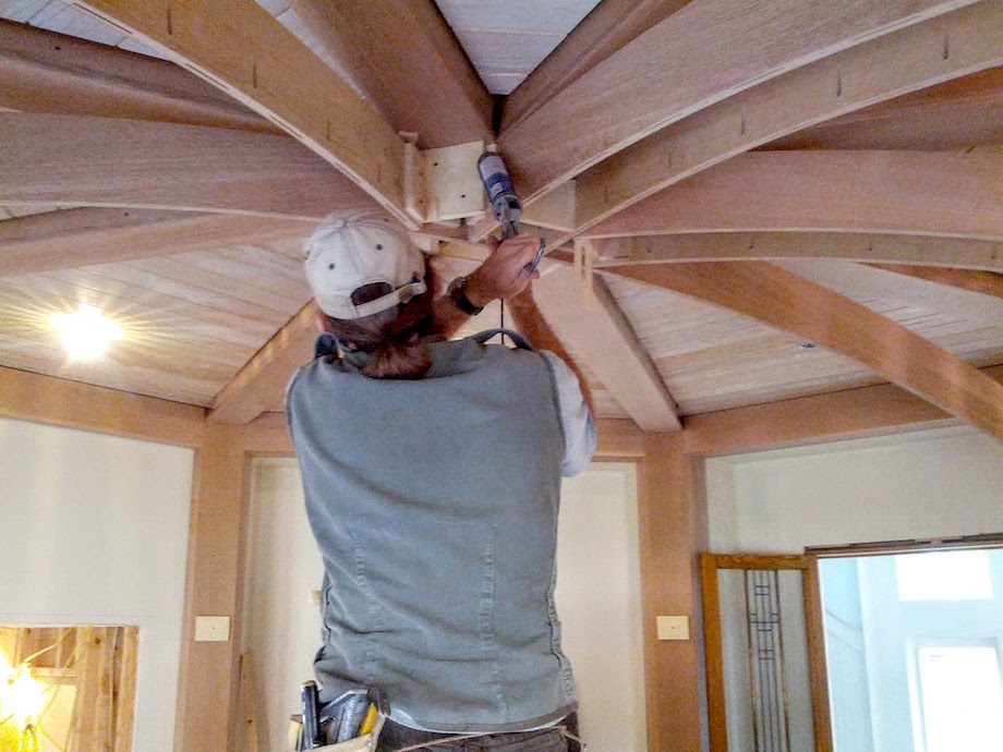 |
Several different configurations of blocking were required for the beam intersections.
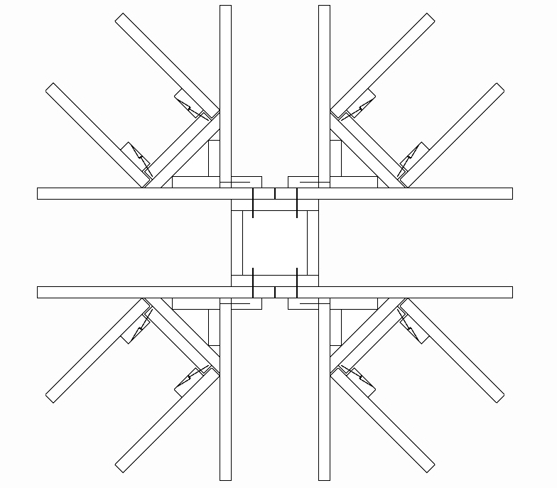 |
The blocks for the last four beams that bisected the quarters were screwed to the inside of the side ahead of time and then pocket-screwed into a perpendicular block installed between the two quarter beams. |
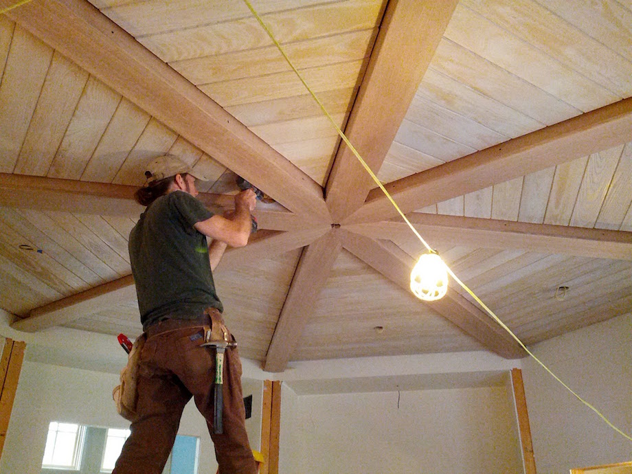
| We were careful to keep the beam sides plumb, align the bottom surfaces, maintain consistent width, and also check that all the beams were “pointing” at the center point. | 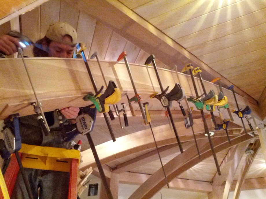 |
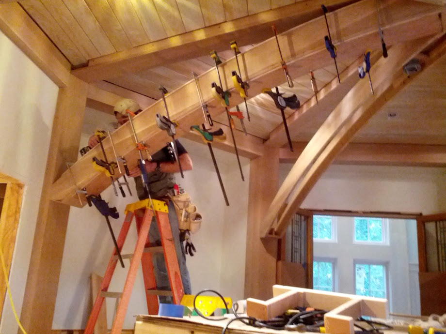 |
Everyone got stabbed in the back with a clamp at least once. |
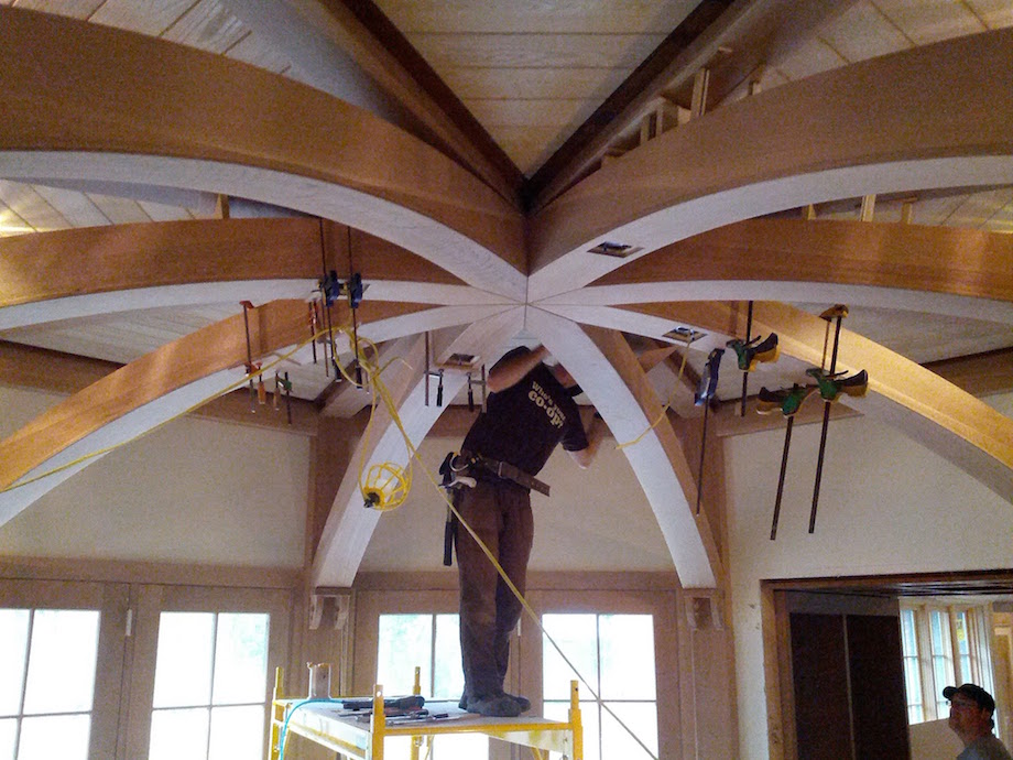
Gluing on the first curved bottom was a bit stressful, but it quickly became routine. The toughest part was figuring out how to keep them from shifting along the arc while being clamped into place. The points at the top were cut using a jig and a circular saw, while the bottoms were run wild to be cut in place later.
| We did the four that didn’t touch first to minimize any accumulated error. | 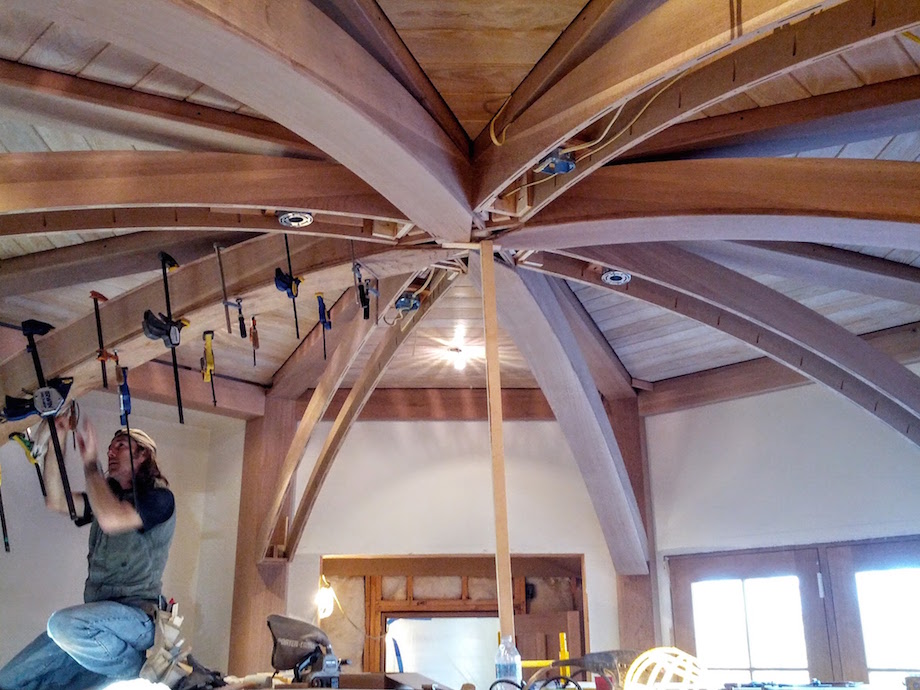 |
| The last four took substantially longer, and getting the last bottom installed was a significant moment. | 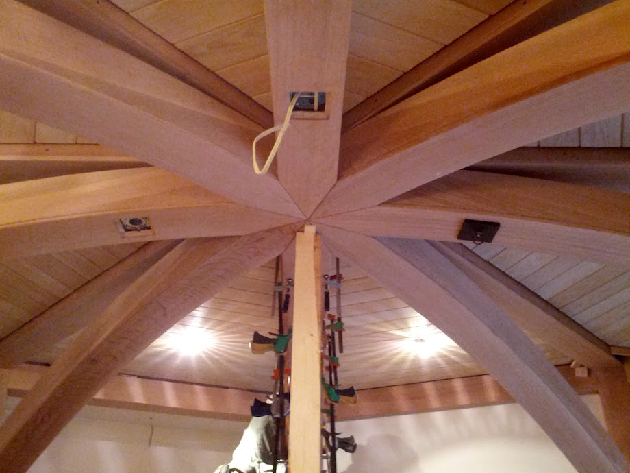 |
| The beam bottoms were cut off flush with the sides in preparation for installing the corbels. We shimmed the jig tight off the floor and positively indexed the biscuit joiner to cut a biscuit slot which would be used to reinforce the joint between the corbel and the column. | 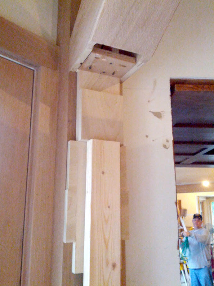 |
| We installed the shop-made corbels with biscuits and PL, and we screwed them from above through a plywood cleat. | 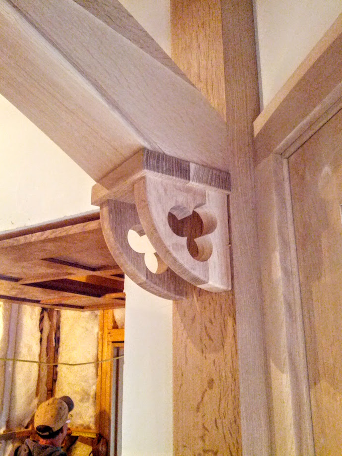 |
The flat beam trim was installed prefinished. We built some simple jigs that allowed us to quickly measure lengths into the acute angles with a laser measure—basically a “V” with each leg exactly 10 in. long. Shooting between two jigs and adding 20 in. was surprisingly accurate; we only had a few recuts around the entire room.
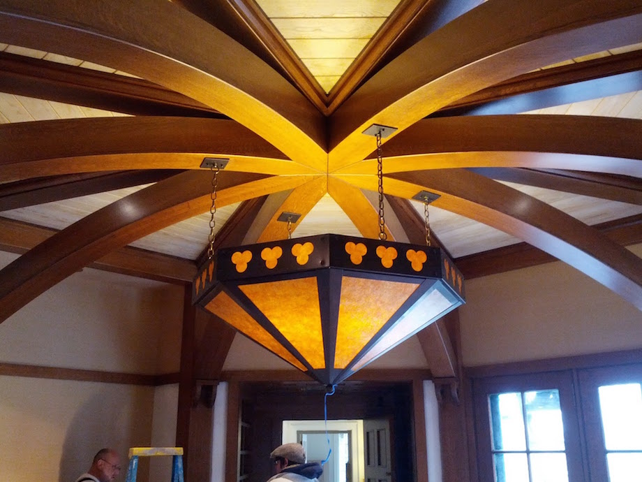
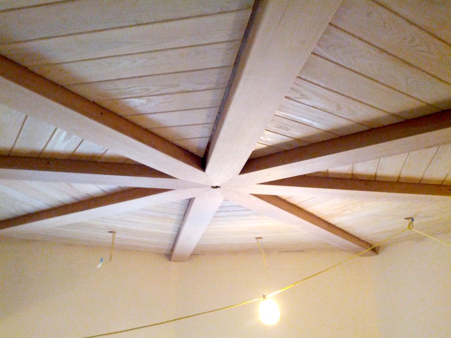
The finished ceiling!
This project was a superb lesson in patience, teamwork, respecting your material, and breaking complicated assemblies down into individual parts that could be attended to independently. This ceiling marked the beginning of a new era in my approach to the work, and gave me a taste for specialty rooms. The intersection of handsome wood and a complex design is something I won’t forget anytime soon.
Special thanks to Josh Andrews and Jerry Jennings for helping brainstorm the ceiling, and to Jason Dunaway and JD Dimick for contributing their skills.
AARON,
Holy crap, what a beautiful project, and sooooo well documented! Your process was as elegant as the finished product. I LOVE the jig you made for cutting the angles on the flat beams. Put a huge smile of approval on this former boat joiner’s face! Thanks so much for sharing with us.
Roe Osborn
Wonderful article and a beautiful project. Thanks for sharing it with us. I was curious as to how you cut the long sweeping curves in the MDF on those long curved flying beams. Jigsaw? Band saw?
Thanks again!
Wayne –
The curved beam sides came to us precut from the shop. I think they used a router and trammel to cut them, but it’s also possible it was a CNC.
Nicely explained.
And it is worth taking a moment to relish those jobs that are both challenging and fun…
Craig Savage
Awesome article, Aaron. Very nice job. Thanks for sharing.
Dan
That right there is some amazing skill and patience like you said. What craftsmanship on your whole team. Great to know the art is still alive. Hope you bought everyone a case of beer when that was done!
nice job and details
Putting the craft in craftsmanship. Great job.
W…O…W…!!!
Beautiful job Aaron! Approximately, how many man hours did you have in this job?
Dave –
The crew and I were trimming out the rest of the house before, during, and after this dining room. I would guess we had about 700-800 man-hours on what is shown in the article.
What a magnificent job. You do our trade proud. Best of luck with more of that.
Very beautiful. Thanks for sharing the details of this wonderful work.
Amazing work!
So happy to see craftsmen creating something so beautiful and balanced.
Hope you got PAID- you deserve every penny I’m sure.
Awesome! So nice to see a truely custom room, you guys did a great job!!
Ken Williams
Very nice work. Well thought out and executed.
Great looking ceiling.
I believe you said that the sides of the curved beams were brought in from a shop . How about the bottoms of the curved beams ? We’re they made the same way and did they just flush out with the sides of the beams ? Great job guys! !!
Steve –
The bottoms were laminated (three layers) and curved to the approximate radius by the shop. They had relaxed a bit by the time they were installed, which is why it was tricky to clamp them up and keep the center points tight. We had to loosely clamp the center to align the curve better, and then clamp the top end at the point really tight before working our way back down the beam. In addition to clamps, we drove pocket screws through the sides down into the bottoms.
As far as the bottoms flushing out with the sides, we had biscuits to help with this alignment, and used spacer blocks between the beam sides if necessary to keep things even. Once the glue dried we sanded the beams in place (this is the project where I learned not to sand finer than 120-150 on stain-grade work), taking pains not to sand through the veneer on the sides. Then we routed the roundovers on the bottoms a final time.
Outstanding effort! Extremely well written and photographed project. Beautiful work, you should be proud.
Wow. That is amazing. Great piece of finished work and great article. Thanks for taking the time to share with us.
Aaron, this is bananas! I was at the Katz Roadshow today and Gary was raving about this job to the audience. I thought he was overselling you a bit, but now that I see your work, he didn’t do you any justice at all. Amazing job!
All –
Thank you very much for your kind words. It’s been very encouraging to read your feedback. I wish there was a way to meet you all in person and hear the things you’ve learned.
Gratefully,
Aaron
Thanks for sharing this fantastic combination of craftmanship, geometry, engineering, ingenuity, and artistry. Congratulations to you and your team.
This is such an incredibly amazing job! Not only beautiful but the craftsmanship is just off the charts. I’ve shared this article at least a dozen times already. And I had to laugh.. When I saw the clamps on the curves I thought “that looks dangerous”.. My favorite quote of the article “Everyone got stabbed in the back with a clamp at least once.”. :). Great job!
I am Irish living in Ireland, Just saw your mastery in carpentry. What a wonderfully crafted ceiling, what can be done with wood in the hands of a craftsman.
Well done to your team, I’ve loved woodwork for many years, and admired many carpenters for their work. At 87 years old I have examined many joints,
Thanks for sharing and showing the art of woodworking is still alive and in very good health—long may it live, Tom Smith, Waterford, Ireland.